Part 1: System cardDel 1: Systemkort
1. Core Function
Sacrificial anodes and Impressed Current Cathodic Protection (ICCP) arrest galvanic corrosion by polarizing a ship's submerged steel hull and bronze propeller into a cathodic state1. Zinc or aluminum-indium sacrificial anodes corrode preferentially without external power, whereas ICCP converts AC supply into regulated DC current from Mixed Metal Oxide hull anodes2. Separately, Marine Growth Prevention Systems (MGPS / ICAF) dose seawater intakes with electrolytic copper ions to prevent barnacle and mussel settlement, paired with aluminum or ferrous ions forming protective internal pipe films5.
2. Primary Operational Tasks
- Hull Galvanic Corrosion Suppression: Polarizes submerged hull steel into a protected potential band—typically -800 to -850 mV or more negative versus Ag/AgCl (within an operating limit down to -1,150 mV)—halting iron dissolution across seawater-exposed plating and weld seams6.
- Propeller & Rudder Shaft Grounding: Establishes a low-resistance bypass (≤0.001–0.01 Ω) across insulating bearing oil films and steering stocks via silver-graphite slip rings and copper bonding straps, preventing bearing spark erosion while extending cathodic protection to bronze propellers11.
- Continuous Hull Potential Monitoring: Tracks hull-to-seawater electrical potential using zinc or silver/silver-chloride reference electrodes, modulating ICCP DC output automatically and triggering under- or over-protection alarms4.
- Sea-Chest Biofouling & Mussel Prevention: Releases controlled cupric (Cu²⁺) ions inside sea chests and strainers to inhibit barnacles, mussels, and algae from fouling cooling circuits and heat exchangers5.
- Recess & Internal Conditioning: Supplements hull ICCP with sacrificial anodes inside shielded sea chests, bow thrusters, rudder flaps, and ballast tanks while MGPS aluminum or ferrous anodes deposit protective internal pipe layers5.
3. System Interconnections
Inputs: Shipboard AC electrical distribution (440 V AC from the main switchboard for standard ICCP Transformer-Rectifier units) powers both ICCP and MGPS control panels4. Hull-mounted Zinc (Zn) or Silver/Silver-Chloride (Ag/AgCl) reference electrodes transmit continuous hull-to-seawater potential readings to the ICCP automatic controller2. On the propulsion line, a dedicated single silver-graphite monitoring brush reads shaft-to-hull potential across the slip ring (for local mV displays or 4–20 mA automation telemetry), while MGPS control panels receive channel current setpoints sized to seawater flow (for example, 0.1–9.9 A per anode channel on commercial units)1.
Outputs: ICCP Transformer-Rectifiers supply regulated low-voltage DC protective current—positive (+) terminal wired to flush hull-mounted Mixed Metal Oxide (MMO) or platinized titanium anodes and negative (-) return bonded to the steel hull—to hold target cathodic polarization2. MGPS units drive controlled DC current through sea-chest and strainer anodes to dose biocidal copper ions and conditioning aluminum or iron ions into cooling systems5. Diagnostic outputs include anode voltage and current logs, reference-cell mV readouts, under/over-protection alarms (-850 mV and -1,150 mV vs. Ag/AgCl under Lloyd's Register limits), shaft-earthing alarms (above 40 mV per ABS or 50–80 mV per OEM thresholds), and MGPS high/low-current alarms1.
4. Redundancy & Criticality
Classification rules require symmetrical port-and-starboard ICCP anode and reference cell layouts, with vessels exceeding 175 m in length fitted with a second independent forward ICCP zone in addition to stern protection13. At each dry-docking, hull-mounted ICCP anodes, dielectric shields, and reference electrodes (~10-year service life) undergo external inspection because replacement afloat requires specialized underwater dry habitats4. Sacrificial anodes typically last 1–5 years depending on vessel sizing and are inspected visually and dimensionally against DNV-RP-B401 utilization factors (0.80–0.90) before end-of-life shrinkage restricts current output; no standalone 75% or 80% class condemnation threshold was documented in the reviewed standards3.
In hazardous cargo environments, Lloyd's Register rules ban ICCP in all internal tanks, prohibit magnesium anodes in or adjacent to tanks holding flammable vapors (restricting them to vented water-ballast tanks), and restrict internal aluminum anodes to locations with ≤275 J drop energy clear of tank hatches10. At tanker berths, ISGOTT mandates terminal-provided electrical isolation (such as insulating flanges or hoses) across cargo connections to interrupt CP and stray currents, alongside advance coordination with terminal managers regarding external ICCP operation23; detailed classification rules on external ICCP cable cofferdams across tanker hazardous zones were not present in the consulted regulatory excerpts13. Continuous operational integrity further relies on routine weekly shaft slip-ring checks and monthly inspections of flexible braided copper rudder bonding straps4.
Part 2: Technical deep diveDel 2: Teknisk dybdeanalyse
1. Electrochemical Corrosion & Sacrificial Anodes
Galvanic corrosion occurs whenever three elements coincide: two dissimilar metals possessing different electrochemical potentials, a metallic path permitting electron flow, and a continuous ionic electrolyte26. Open-ocean seawater exhibits a low resistivity of approximately 20–30 Ω·cm (0.2–0.3 Ω·m), acting as an aggressive electrolyte—one marine equipment supplier estimates corrosion progresses roughly five times faster in saltwater than in freshwater8. Within this cell, the less noble (more negative potential) metal acts as the anode and dissolves into ions, while electrons flow through the hull structure to the more noble (more positive) cathode, where oxygen reduction or hydrogen evolution consumes those electrons without corroding the noble surface26.
On ships, severe galvanic couples form directly between structural and propulsion alloys. In flowing seawater against a Saturated Calomel Electrode (SCE), mild steel and cast iron sit at -0.60 to -0.72 V and low-alloy steel at -0.57 to -0.63 V, whereas marine propeller alloys sit substantially more noble: manganese bronze measures -0.26 to -0.34 V vs. SCE and nickel-aluminum bronze measures -0.14 to -0.22 V vs. SCE, establishing a driving galvanic differential of roughly 0.23 to 0.58 V29. When coupled electrically, the bronze propeller forces rapid anodic dissolution of adjacent hull steel6. Area ratio amplifies this attack: because hull plating is painted while propellers remain bare, any paint pinhole (holiday) exposes a tiny anodic steel spot linked to an enormous noble bronze cathode, concentrating corrosion current onto localized pits26. Similar micro-galvanic cells arise along hull weld seams where filler metallurgy differs from parent plate steel, leading to preferential seam disintegration6.
Sacrificial (galvanic) anodes prevent corrosion by coupling a deliberately more active alloy to the hull so that the entire steel structure polarizes below its free-corroding potential—reaching ≤-0.80 V vs. Ag/AgCl in aerobic seawater, or ≤-0.90 V vs. Ag/AgCl where sulfate-reducing bacteria (SRB) create anaerobic conditions3. Pure zinc, aluminum, and magnesium are unsuitable because self-corrosion or oxide passivation impairs output, requiring tight alloy specifications13.
Anode Alloy Family and Standards | Closed-Circuit Potential vs. Ag/AgCl / Seawater | Practical Electrochemical Capacity (ε) | Practical Consumption Rate | Primary Marine Suitability and Operational Limits |
|---|---|---|---|---|
Zinc (Zn-Al-Cd / Zn-Al) (ASTM B418 Type I/II, EN 12496 Z1) | -1.03 to -1.05 V (Type II: -1.00 V; sediment: -0.99 V)13 | 750–780 Ah/kg (theoretical 820 Ah/kg; Type II: 760 Ah/kg)13 | 11.2 kg/(A·yr) seawater; 11.8 kg/(A·yr) sediment13 | Seawater, brackish, and freshwater (requires no chloride activation); capped at 50–60°C and pH 5–10; suited to mud/sediment and hazardous areas where aluminum is restricted8. |
Aluminum-Indium (Al-Zn-In) (DNV-RP-B401, Mil-A-24779, EN 12496 A1–A3) | -1.05 to -1.10 V (net ~0.25–0.30 V driving voltage vs. protected steel)21 | 2,400–2,651 Ah/kg tested; 2,000 Ah/kg DNV design (theoretical 2,980 Ah/kg)8 | 3.3–3.5 kg/(A·yr) seawater; 4.4 kg/(A·yr) sediment31 | Primary hull and offshore alloy (80–85% vendor-rated efficiency); requires salinity >5 g/kg (resistivity <2 Ω·m); loses capacity at elevated temperature and in SRB mud13. |
Magnesium (AZ63B / M1C) (ASTM B843, EN 12496 M1/M2) | -1.50 V (M1) to -1.70 V (M2) in seawater (-1.45 to -1.62 V vs. Cu/CuSO₄ in soil/freshwater)13 | 1,100–1,230 Ah/kg (1,200 Ah/kg ABS/EN seawater value; 50–55% efficiency)13 | 7.12–7.96 kg/(A·yr) (7.3 kg/(A·yr) ABS/EN seawater value)13 | Freshwater and high-resistivity soils (≤100 Ω·m) only. Excessive voltage and low efficiency preclude seawater hull use; banned on aluminum hulls and near flammable cargo vapors10. |
Sacrificial anode sizing under DNV-RP-B401 computes initial, mean, and end-of-life current demand from wetted steel area ( ), time-dependent coating breakdown factor (
 ), and environment-specific design current density (
 )8:

Vessel speed and operating conditions sharply raise  . ABS design guidance specifies 100–200 mA/m² (bare steel) and 5–15 mA/m² (coated steel) at ≤2 knots without tidal flow, rising to 150–250 mA/m² (bare) and 7–20 mA/m² (coated) under tidal influence, 220–350 mA/m² (bare) and 11–28 mA/m² (coated) at 2–20 knots, 350–500 mA/m² (bare) and 18–40 mA/m² (coated) at ≥20 knots, 500–750 mA/m² (bare) and 35–90 mA/m² (coated) for ice-going vessels, and ≥500 mA/m² on bare propeller surfaces13. Required net anode mass (
 , in kg) over design life (
 , in years) is calculated as8:
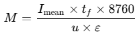
Here  represents the anode utilization factor (0.80 for stand-off anodes, 0.85–0.90 for flush/bracelet designs) and
 is practical electrochemical capacity (Ah/kg), related to consumption rate (
 , in kg/(A·yr)) via
 8. Temperature and microbiology further derate aluminum anodes: ABS applies
 (Ah/kg) between 20°C and 80°C, while a 2026 laboratory study in SRB-laden marine mud measured average Al-alloy capacity dropping to 1,281.28 Ah/kg (44.82% efficiency)13. Anode count (
 ) must also satisfy both initial and end-of-life current demand because depleted anodes shrink and exhibit higher electrolyte resistance (
 )8.
Because Al-Zn-In requires roughly one-third the mass per ampere-year of zinc, aluminum dominates open-sea external hulls, while zinc serves brackish transitions, warmer recesses (up to 50–60°C), and hazardous tank spaces13. Even on ICCP-protected ships, sacrificial anodes are strategically placed inside geometrically shielded or turbulent zones: sea chests and scoop openings, bow thruster recesses, rudders and separate rudder flaps, stern hull frames near propellers, and bow surfaces subject to high water velocity13. Internal tank anodes must be welded to structural stiffener webs at least 25 mm clear of free edges—never directly onto main hull shell plating—to avoid stress risers10.
2. Impressed Current Cathodic Protection (ICCP) Architecture
For medium and large vessels, ICCP overcomes the mass penalty, drag, and 1–5 year renewal cycle of sacrificial systems, delivering vendor-stated service lifespans of 15–25 years with automated current modulation across changing speeds, temperatures, salinities, and paint aging2. Shipboard 440 V AC power enters a Transformer-Rectifier (T/R) control cabinet that steps down and rectifies AC into controlled low-voltage DC (industrial ICCP power supplies typically operate in the 18–30 V DC output range), wiring the positive (+) output to insulated hull anodes and grounding the negative (-) return solidly to the steel hull4.
Modern ICCP hull anodes employ Mixed Metal Oxide (MMO) coatings—supplier specifications cite ruthenium-iridium (Ru-Ir) formulations for seawater and iridium-tantalum (Ir-Ta) coatings for chloride-rich or elevated-temperature service at 3–8 g/m² minimum loading—thermally bonded onto ASTM B265 or B348 Grade 1 or Grade 2 titanium substrates, alongside platinized titanium, niobium, tantalum, and legacy lead/silver alloy anodes permitted by class10. MMO-coated titanium acts almost non-consumably, exhibiting vendor-reported wear rates of 0.001–0.01 g/(A·yr) (1–6 mg/(A·yr)) while sustaining high discharge current densities of 1,000–2,000 A/m²27. For platinized titanium anodes, ABS notes that maximum operating voltage is restricted by the anodic breakdown potential of the titanium substrate; specific numerical breakdown limits from ABS Section 4 Table 1 were unavailable in the reviewed document excerpt13.
To minimize hydrodynamic drag and resist physical damage from anchor chains or tugs, hull ICCP anodes are shaped as low-profile circular, elliptical, or linear discs bolted into hull recesses and encapsulated with waterproof epoxy resin13. Because intense DC current discharge creates steep local potential gradients in seawater, every hull anode is surrounded by an epoxy-insulated dielectric shield10. Lloyd's Register rules mandate dielectric shields sized to prevent negative potentials of -1.70 V vs. Ag/AgCl and below on adjacent hull steel while spreading protective current evenly across distant hull plating10.
Automatic T/R regulation depends on closed-loop feedback from hull-mounted reference electrodes—either high-purity Zinc (Zn) cells (~10-year life) or Silver/Silver-Chloride (Ag/AgCl) seawater electrodes13. Operators must distinguish carefully between Ag/AgCl and Zn reference conventions:
Reference Scale and Steel Condition | Target or Limit Potential | Regulatory and Engineering Interpretation |
|---|---|---|
Carbon steel vs. Ag/AgCl / Seawater (Standard Target) | -800 to -850 mV | Optimal protection band (-850 mV vs. Cu/CuSO₄ equals roughly -800 mV vs. Ag/AgCl)8. |
Carbon steel vs. Ag/AgCl / Seawater (LR ICCP Limits) | -850 mV (Under) / -1,150 mV (Over) | Lloyd's Register operating band requiring alarms; potentials below -1,200 mV risk coating damage10. |
Special Steels and Aluminum vs. Ag/AgCl / Seawater | -950 mV (HSS max); -900 to -1,150 mV (Al) | LR cap for high-strength steel (>700 N/mm²) to mitigate hydrogen cracking, and limits for aluminum hulls10. |
Anaerobic SRB Steel vs. Ag/AgCl / Seawater | -900 to -1,100 mV | Deeper polarization required where sulfate-reducing bacteria are present8. |
Carbon steel vs. Zinc Reference Electrode (Shipboard Panel) | +220 mV optimal (+400 to +600 mV unprotected) | Because a Zn reference sits near -1,030 mV vs. Ag/AgCl, protected hull steel reads positive relative to Zn15. |
ABS rules dictate strict port-starboard symmetry in ICCP anode and reference cell positioning13. On ships ≥150 m, stern anodes must sit at least 15 m forward of the propeller (reducible to 5 m on small craft), while ships >175 m require an independent second ICCP system at the bow13. Control reference cells must sit well outside anode voltage plumes—15–20 m (or at least ~10% of overall vessel length) away from their paired anode, positioned between stern anodes and the propeller (and forward of bow anodes if fitted)—with additional monitoring cells placed near propellers and on the dielectric shield periphery to verify both minimum protection and over-protection limits10. Automatic T/R cabinets use thyristor control and regulation boards to adjust DC output continuously in Auto mode while displaying anode current, anode voltage, and individual/averaged reference cell mV readings, alongside a Manual control mode for abnormal water conditions2.
3. Propeller Shaft & Rudder Earthing (Slip Rings)
Even though a bronze propeller bolts directly to the tailshaft, a rotating propulsion shaft becomes electrically isolated from the steel hull by lubricating oil films inside stern-tube, main engine, and shaft bearings, as well as nonmetallic bearing materials11. Left ungrounded, this electrical break prevents ICCP or hull sacrificial currents from reaching the propeller and boss, leaving the bronze blades vulnerable to corrosion and cavitation damage1. Worse still, potential differences generated across the bearing oil film cause intermittent electrical arcing—termed spark erosion—that severely pits shaft bearings and gearbox surfaces11.
Propeller shaft earthing devices bypass bearing insulation by establishing a dedicated low-resistance short between the rotating shaft and the hull1. Manufacturers recommend mounting the slip ring as far aft along the shaft line as possible—ideally between the aft stern seal and the furthest aft bearing—to intercept stray and CP currents near the propeller18. The assembly uses a copper slip ring or clamp band fitted with a solid silver contact track (vendor-rated at a 20-year service life) contacted by spring-loaded silver-graphite brushes (such as 80% silver / 20% graphite compositions rated for a minimum 1-year life by K.C. Ltd., or 4–12 months in field service per CORROSION)1. Best practice separates power grounding from instrumentation: a double brush holder carries grounding current to the hull structure, while a dedicated single brush holder connects to a local or remote (4–20 mA) millivolt meter so earthing contact drop does not distort diagnostic voltage measurements1. ABS rules cap shaft-to-hull contact resistance at ≤0.001 Ω for water-lubricated bearings and ≤0.01 Ω for oil-lubricated bearings (high-performance slip rings measure <0.001 Ω), keeping shaft potential below 40 mV per ABS (while marine vendors specify <50 mV normal limits, or <80 mV green / >80 mV red alarm zones)1.
Rudder stocks experience comparable intermittent electrical isolation across steering-gear movement and rudder bearings14. On every ICCP-fitted vessel, the rudder stock must be bonded to adjacent hull plating using a flexible braided copper strap—for example, a commercial Cathwell unit using 12 × 2.3 mm braided copper rated at 90 A with Ø10 mm bolt lugs—while rudder flaps require independent sacrificial anodes14. Correct installation leaves adequate slack across full rudder travel so the strap is never pulled taut, and utilizes solid tinned bolt-hole lugs rather than clamping bare loose strands, avoiding strand creep, rising contact resistance, and joint heating45. Specific classification society minimum cross-sectional sizing formulas (mm²) for rudder bonding straps were not specified in the consulted excerpts14.
4. Marine Growth Prevention Systems (MGPS / ICAF)
Internal seawater systems—sea chests, suction strainers, condensers, jacket and oil coolers, refrigeration equipment, AC units, and box coolers—face biofouling from barnacles, mussels, and algae that constrict flow and accelerate internal corrosion5. Marine Growth Prevention Systems (MGPS / ICAF) prevent macro-fouling at seawater intakes without bulk chemical dosing5. Crucially, MGPS anodes are not passive sacrificial cathodic protection anodes: they operate on a controlled DC supply (typically adjustable from 0.1 to 9.9 A per channel on commercial controllers) mounted inside sea-chest intakes (such as S355J2 steel cofferdams in 200–1,000 mm lengths), duplex strainer housings allowing ~10-minute cartridge renewal, reaction tanks, or box-cooler bays5.
Anti-fouling action comes from electrolytic copper (Cu) anodes whose controlled dissolution releases cupric ions (Cu²⁺) directly into incoming seawater5. Vendor engineering data from CathodicME reports that continuous copper concentrations below 2 ppb throughout downstream piping prevent barnacles, mussels, and algae from settling while remaining within IMO, EPA, and classification society tolerances5. Because copper acts as a biocide, any vessel operating a copper-based MGPS/ICAF unit inside European Union territorial waters must comply with the EU Biocidal Products Regulation (BPR) Article 95 under Product Type 11 (preservatives for liquid cooling and processing systems), sourcing copper anodes exclusively from Article 95-listed suppliers to prevent Port State Control sanctions or forced system shutdowns48.
To protect downstream seawater piping against corrosion alongside copper dosing, MGPS installations pair copper anodes with either aluminum (Al) or ferrous/soft-iron (Fe) anodes5. Carbon steel and galvanized steel piping circuits employ aluminum anodes, which disperse aluminum ions downstream to deposit a protective anti-corrosive film along sea-chest and pipe interiors5. Conversely, vessels fitted with cupro-nickel (Cu-Ni) piping must substitute ferrous (soft-iron) anodes in place of aluminum; OEM guidance stresses that aluminum and iron MGPS anodes are strictly non-interchangeable without verifying original circuit metallurgy and controller channel settings6. Note that while marine engineering specifications frequently refer to this internal conditioning layer as a protective hydroxide film, the reviewed manufacturer and technical datasheets describe aluminum and ferrous anode conditioning functionally as an anti-corrosive film or layer without specifying its hydroxide precipitation chemistry5.
5. Failure Modes, Over-Protection & Dry-Dock Inspection
Hull corrosion systems fail when electrochemical potential drifts outside safe limits, dielectric barriers degrade, shaft/rudder bonding breaks down, or water resistivity shifts abruptly2.
Excessive negative hull potential—over-protection below Lloyd's Register's -1,150 mV over-protection alarm and particularly past -1,200 mV vs. Ag/AgCl—drives hydrogen evolution at coating scratches and porosities, blistering and lifting paint films in a process known as cathodic disbondment10. On high-strength steels (>700 N/mm² tensile strength), excess negative potential introduces atomic hydrogen that causes Hydrogen-Induced Stress Cracking (HISC) and accelerates fatigue crack propagation, prompting Lloyd's Register to enforce a -950 mV vs. Ag/AgCl cap10. On aluminum hulls, potentials more negative than -1,150 mV vs. Ag/AgCl (or contact with magnesium anodes) cause alkaline dissolution because aluminum is amphoteric10.
Damage to an ICCP anode's insulating dielectric shield exposes adjacent hull steel directly to intense current discharge, dropping local potential toward -1,700 mV vs. Ag/AgCl or below10. This causes severe localized over-protection and coating disbondment near the anode while degrading uniform protective current distribution along the hull4. On the shaft line, worn silver-graphite brushes (reaching service limits within 4–12 months), fouled silver slip-ring tracks, or lost spring tension raise contact resistance past 0.01 Ω and shaft voltage past 40–80 mV, re-initiating bearing spark erosion and propeller pitting1. Similarly, improperly terminated or over-tensioned rudder bonding braids fail at lug ends, isolating the rudder stock14.
Transits into freshwater rivers or brackish ports (resistivity >2 Ω·m, salinity <5 g/kg) dramatically reduce electrolyte conductivity relative to seawater (~20–30 Ω·cm)8. Passive sacrificial output falls as water resistivity climbs, and Al-Zn-In anodes are unsuitable below 5 g/kg salinity under EN 12496 because aluminum relies on chloride activation—leaving zinc anodes as the active choice in brackish/fresh water6. On ICCP-equipped ships, high freshwater resistance diminishes current flow, causing Auto-mode T/R controllers to drive voltage excessively upward and trigger faults2. Crews must monitor T/R readouts during freshwater navigation and shift to reduced Manual settings or follow manufacturer operating procedures until returning to seawater, where Auto mode restores optimal polarization2.
Failure Mode or Condition | Primary Symptoms and Alarms | Root Cause Mechanism | Corrective Action and Prevention |
|---|---|---|---|
ICCP Over-Protection / Disbondment | Hull potential below -1,150 to -1,200 mV vs. Ag/AgCl; paint blistering near anodes10. | Reference cell drift, failed dielectric shield, or Auto-mode fault driving local hydrogen evolution4. | Calibrate control unit and inspect reference cells; repair dielectric shield; verify over-protection alarms (-950 mV cap for HSS)4. |
Shaft Bearing Spark Erosion | Shaft potential >40–50 mV (or >80 mV red alarm); pitted shaft/gearbox bearings1. | Worn silver-graphite brushes (4–12 mo), oily slip-ring track, or poor tension (>0.01 Ω)11. | Clean slip ring weekly; replace worn brushes; keep single monitoring brush isolated from double grounding holder1. |
Freshwater / Port Voltage Fault | T/R output voltage climbs excessively while protection drops; unit fault in river ports2. | High water resistivity (>2 Ω·m) impedes throw; Auto controller forces voltage ceiling2. | Switch to Manual mode or follow OEM freshwater procedure; re-engage Auto upon returning to seawater2. |
MGPS Pipe Pitting / Fouled Coolers | High/low channel current alarms; barnacles in coolers or internal pipe pitting5. | Depleted Cu/Al/Fe anodes, shorted seals, or installing Al instead of Fe on Cu-Ni piping6. | Replace depleted anodes with OEM-matched metallurgy (Fe for Cu-Ni, Al for steel); verify DC amps6. |
Prior to and during dry-docking, marine engineers and classification surveyors follow a structured five-step inspection and commissioning sequence:
- Pre-Dock Potential Survey & External ICCP Inspection: Record pre-dock hull potentials prior to docking, then visually inspect all flush MMO/Pt-Ti anodes, reference electrodes, and surrounding dielectric shields for cracking, epoxy leakage, or physical damage4.
- Pre-Launch Insulation Resistance Testing: Before re-floating, verify that electrical resistance between every ICCP anode and the hull—and between every reference cell and the hull—exceeds 1.0 MΩ, ensuring all active faces are clean, dry, and free of tape or masking dirt that causes false voltage readings15.
- Reference Cell & Sacrificial Anode Renewal: Assess ~10-year reference electrodes and measure sacrificial anode wastage visually and dimensionally against the design-life plan; renew depleted hull, sea-chest, thruster, rudder-flap, and internal tank anodes (welded to stiffener webs ≥25 mm from edges), ensuring active faces remain unpainted10.
- MGPS / ICAF Overhaul: Open sea-chest cofferdams and strainer housings to renew depleted copper, aluminum, or ferrous anodes, inspect mounting sleeves, seals, and cable glands against original drawings, and confirm EU BPR Article 95 compliant copper spares for EU routes16.
- Earthing Verification & Post-Float Commissioning: Inspect and service slip-ring silver tracks, replace worn 80/20 silver-graphite brushes, verify flexible braided copper rudder straps and lugs, and perform post-float ICCP commissioning measurements once fully immersed to verify steady hull polarization (-800 to -850 mV vs. Ag/AgCl, or ~+220 mV vs. Zn reference)1.
References
- Product Shaft Earthing Device - K.C.LTD., https://iccp-mgps.com/product/shaft.php
- ICCP (Impressed Current Cathodic Protection System) for ship hull, https://bbc-smrmarine.com/iccp-impressed-current-cathodic-protection-system-for-ship-hull-corrosion-protection-n35.html
- What is a sacrificial anode and why ICCP systems are a better, https://evac.com/article/what-is-a-sacrificial-anode-and-why-iccp-systems-are-a-better-solution/
- What is vessel cathodic protection and its purpose?, https://chiefengineerlog.com/2022/06/09/what-is-vessel-cathodic-protection-and-its-purpose/
- Marine Growth Prevention System, https://cathodicme.com/services/marine-growth-prevention-system/
- ICCP & MGPS system - ShipServ, https://www.shipserv.com/ShipServ/pages/profiles/219477/documents/ICCP-AND-MGPS-SERVICE.pdf
- Anti Fouling - BAC IMPALLOY, https://www.bacimpalloy.com/products/vessels/anti-fouling/
- CP Anode Sizing: DNV-RP-B401, https://www.sahawatthanakit1988.com/en/insights/cathodic-protection-anode-sizing-design-dnv-rp-b401-iso-12696-thailand
- Marine Corrosion and Protection Insights | PDF - Scribd, https://www.scribd.com/document/764759497/Chris-Googan-Marine-Corrosion-and-Cathodic-Protection-2022-CRC-Press-Libgen-li
- Section 4 Cathodic Protection (CP) - imorules, https://www.imorules.com/LRMAT_CH15_4.html
- Shaft grounding - Cathwell, https://cathwell.com/industries/ships/shaft-grounding/
- Shaft earthing device - Wärtsilä, https://www.wartsila.com/encyclopedia/term/shaft-earthing-device
- https://ww2.eagle.org/content/dam/eagle/rules-and-guides/current/conventional_ocean_service/289_cathodicprotectionofships_2017/cathodic-protection-gn-dec17.pdf
- Why grounding the rudder? - Cathwell, https://cathwell.com/why-earthing-the-rudder/
- ICCP System Operation Manual | PDF | Anode | Corrosion - Scribd, https://www.scribd.com/document/713085896/ICCP-Manual
- MGPS Anodes for Marine Growth Prevention Systems - Hele Titanium, https://heletitanium.com/titanium-anode/mgps-anodes/
- Anti-Fouling System - Marine Growth Preventing System (M.G.P.S.), https://iccp-mgps.com/product/mgps.php
- Cathelco Shaft Earthing systems - Evac, https://evac.com/products/shaft-earthing/
- Propeller Shaft Grounding - corrosion.nl, https://www.corrosion.nl/wp-content/uploads/2023/02/CORROSION_PSG_Booklet-2.pdf
- ICCP Anodes (Impressed Current Cathodic Protection) - NedMarine, https://nedmarine.com/cathodic-protection/iccp/
- Offshore CP Design (DNV-RP-B401) | Mitcorr Technical Guide Series, https://mitcorr.com/resources/offshore-cp-design.html
- Section 5 Cathodic protection in tanks, https://www.imorules.com/GUID-B31B0D88-106E-40C0-A4E3-08AFF8E7582E.html
- 17.1 Siting of Electrical Equipment, https://studfile.net/preview/1665732/page:18/
- Foreword to Fourth Edition - pfri.uniri.hr, https://www.pfri.uniri.hr/web/dokumenti/uploads_nastava/20180405_093425_bernecic_ISGOTT_4TH_EDITION.pdf
- ISGOTT 6th Edition 2020 - BigCommerce, https://cdn11.bigcommerce.com/s-ya3gab2q5e/content/pdf/BP103356.pdf
- Galvanic Series Chart: 12 Metals Ranked in Seawater (Volts), https://www.fabrico.io/blog/galvanic-corrosion/
- How to Choose Cathodic Protection Titanium Anode Supplier: ICCP, https://plmesh.com/how-to-choose-cathodic-protection-titanium-anode-supplier-iccp-vs-mmo-vs-sacrificial-anodes/
- What is impressed current cathodic protection? - Cathelco - Evac, https://evac.com/blog/what-is-impressed-current-cathodic-protection/
- Seawater Corrosion - The Australasian Corrosion Association Ltd, https://www.corrosion.com.au/foundation/resources/student-teacher-resources/seawater-corrosion/
- Cathodic protection of jack-up rigs (PDF) - Havtil, https://www.havtil.no/contentassets/29e2662209804c23870d29941032717f/cathodic-protection-of-jack-up-rigs.pdf
- Magnesium, Zinc or Aluminum Anode? Selection Guide - CathPro, https://www.cathprocp.com/guides/magnesium-vs-zinc-vs-aluminum-anodes.html
- Aluminium anodes - Cathwell, https://cathwell.com/tech-categories/data-sheet/aluminium-sacrificial-anodes/
- Aluminum Anode vs Magnesium Anode: Cathodic Protection, https://chinatitaniumfactory.com/blog/Aluminum-Anode-vs-Magnesium-Anode.html
- Effect of SRB on the Electrochemical Performance of Aluminum, https://www.mdpi.com/2079-6412/16/1/26
- Magnesium Anodes By GESIT: High-Performance Solutions, https://gesitnazelo.com/magnesium-anodes/
- (PDF) The Selection of Magnesium alloys as Sacrificial Anode for, https://www.researchgate.net/publication/320100251_The_Selection_of_Magnesium_alloys_as_Sacrificial_Anode_for_the_Cathodic_Protection_of_Underground_Steel_Structure
- Mitigation of corrosion by cathodic protection, https://www.icorr.org/wp-content/uploads/2020/06/08a-Mitigation-of-Corrosion-by-Cathodic-Protection.pdf
- MMO Disc Anode for Ship ICCP System (Round Shape), https://jenningsanodes.com/product/mmo-disc-hull-anode-circular-shape/
- Jetty ICCP Anode Data Sheet - Pipeline Maintenance Limited, http://pipelinemaintenance.co.uk/data/Jetty%20anode.pdf
- The Introduction and Working Principle of ICCP Titanium Anode, https://yunchmetal.com/the-introduction-and-working-principle-of-iccp-titanium-anode/
- Cathodic Protection Guidelines for Ships | PDF | Anode - Scribd, https://www.scribd.com/document/450863594/Cathodic-Protection-Gn-Dec17
- Impressed Current Cathodic Protection Systems (ICCP) - MCPS LTD, http://www.mcpsltd.com/impressedcurrent_cathodicprotection.html
- ICCP System for Vessel N198 | PDF | Corrosion | Anode - Scribd, https://www.scribd.com/document/824544304/N198-ICCP-FINAL-DRAWING
- Marine & Offshore: ICCP & Slip Rings | MPE Cathodic AS, https://www.mpecathodic.no/marine--offshore
- Copper Braid and Braided Straps: Flexible Bonding, Earthing and, https://www.yominelectric.com/blog/copper-braid-guide
- RULES FOR THE CLASSIFICATION OF NAVAL SHIPS - Türk Loydu, https://www.turkloydu.org/pdf-files/turk-loydu-kurallari/cilt-e/chapter-105-naval-ship-technology-electrical-installations-2022-JAN.pdf
- Aluminium MGPS/ICAF anode Ø150 sea water intake w/cofferdam, https://cathwell.com/product/aluminium-mgps-icaf-anode-o150-sea-water-intake-w-cofferdam/
- Staying compliant with copper based MGPS/ICAF systems - Cathwell, https://cathwell.com/article-95-explained-staying-compliant-with-copper-based-mgps-icaf-systems/
- Simulation-based Optimization of Impressed Current Cathodic, https://orbit.dtu.dk/files/458179731/1-s2.0-S0029801826034839-main.pdf
- (PDF) Cathodic Protection: A Brief Primer - ResearchGate, https://www.researchgate.net/publication/320452134_Cathodic_Protection_A_Brief_Primer
- CATHODIC PROTECTION OF OFFSHORE STRUCTURES, https://ww2.eagle.org/content/dam/eagle/rules-and-guides/current/offshore/306-cathodicprotection-offshore-structures/cathodic-protection-offshore-gn-dec18.pdf
- ICCP (Impressed Current Cathodic Protection System) for ship hull, https://bbc-smrmarine.com/iccp-impressed-current-cathodic-protection-system-for-ship-hull-corrosion-protection-n36.html