Navigation lights at nightLanterneføring om natten
Interactive diagramInteraktivt diagram
VesselFartøy
You see her fromDu ser henne fra
Power-driven vessel ≥ 50 mMaskindrevet fartøy ≥ 50 m
Lights you see, top to bottomLys du ser, ovenfra og ned
- 2 × masthead light (white)2 × toplanterne (hvit)
- port sidelight (red)babord sidelanterne (rød)
- starboard sidelight (green)styrbord sidelanterne (grønn)
Under way. Two masthead lights, the after one higher: how they line up tells you her heading, and they open and close as she alters course.Under fart. To toplanterner, den aktre høyest: hvordan de står i forhold til hverandre viser kursen, og de åpner og lukker seg når hun endrer kurs.
By dayOm dagen
No day shape.Ingen dagsignalfigur.
COLREG Rules 21–30. Lights not to scale; side arcs 112.5°, masthead 225°, sternlight 135°. Optional lights are mentioned in the summary, not drawn.Sjøveisreglene (COLREG) regel 21–30. Lysene er ikke i målestokk; sidelanterner 112,5°, toplanterne 225°, akterlanterne 135°. Valgfrie lys er nevnt i teksten, ikke tegnet.
Part 1: System cardDel 1: Systemkort
1. Core Function
Shipboard visual and acoustic signaling systems communicate a vessel’s presence, aspect, size category, operational status, and maneuvering intentions to surrounding traffic across day, night, and restricted visibility1. Under COLREGs, navigation lights project color- and arc-coded optical beams from sunset to sunrise and in poor visibility2, black day shapes convey operational status and physical constraints during daylight7, and whistles, bells, and gongs broadcast standardized acoustic signals to coordinate collision avoidance and indicate distress4.
2. Primary Operational Tasks
- Night Aspect & Length Indication: Masthead, sidelight, and sternlight arcs reveal a vessel’s heading and aspect relative to surrounding traffic, while a second masthead light distinguishes power-driven vessels 50 m or longer1.
- Special Operational Status Signaling: Vertical all-round light arrays and black day shapes identify Not Under Command (NUC), Restricted in Ability to Manoeuvre (RAM), Constrained by Draught (CBD), towing (exceeding 200 m), fishing, anchored, and aground status, while white-over-red all-round lights identify pilotage duty7.
- Restricted Visibility Fog Signals: Timed whistle, bell, and gong sequences sounded at intervals of at most 1–2 minutes communicate way through the water, stopped-underway status, towing, NUC/RAM/CBD/fishing/sailing operations, or anchoring and grounding4.
- Close-Quarters Maneuvering & Warning: Whistle blasts and synchronized white light flashes announce course alterations, astern propulsion, narrow-channel overtaking intentions, blind-bend approaches, and five-blast doubt or warning signals5.
- Attention & Distress Alerting: Searchlights or unambiguous light and sound signals draw attention to danger under Rule 36, while Annex IV signals—including continuous fog-apparatus sounding, pyrotechnics, flags, and Digital Selective Calling (DSC) alerts—indicate distress and need of assistance9.
3. System Interconnections
- Inputs: Navigation light controllers draw dual power feeds from the main switchboard (typically 115V/230V AC or 24V DC) and the emergency switchboard / 24V DC battery or emergency generator source17. Air-driven diaphragm tyfons receive compressed air (6–40 bar across commercial pneumatic designs) via condensate filters and dual-coil solenoid valves22, whereas electric piston horns draw 3-phase AC mains (230–690V)25. Bridge automatic fog-signal timers accept watchkeeper mode selections to drive timed solenoid or contactor coils and thermostatic anti-icing heaters23.
- Outputs: Bridge Navigation Light Control Panels (NLCs) output visual ON/OFF/fault indicators, audible failure buzzers, and bi-directional serial telemetry (IEC 61162 / NMEA 0183) to Voyage Data Recorders (VDR) and integrated bridge alarm systems1. External emitters propagate CIE-chromaticity optical beams visible from 1 to 6 nautical miles (NM)6, 70–700 Hz whistle blasts audible over 0.5–2 NM32, and ≥110 dB bell and gong strikes32.
4. Redundancy & Criticality
COLREG Annex I and Annex III enforce strict optical geometry, luminous intensity, acoustic frequency, and sound pressure level thresholds subject to Flag State approval6. Under IMO Resolution MSC.253(83) (for installations from 1 January 2009) and SOLAS Chapter II-1 Regulations 42–43, ships of 50 m or more require duplicated masthead, sidelight, and sternlight fixtures or duplicate lamps on isolated branch circuits backed by emergency power for 18 hours on cargo ships and 36 hours on passenger ships1. Because LED output decays without reducing electrical current, MSC.253(83) specifies either an active low-intensity alarm or strict replacement within a manufacturer-certified lifespan1.
Part 2: Technical deep diveDel 2: Teknisk dybdeanalyse
1. Navigation Lights & COLREG Annex I Geometry
Navigation lights convey vessel heading, size band, and operational status through prescribed horizontal sectors, color boundaries, and vertical separation rules codified in COLREG Part C (Rules 20–31) and Annex I3. Under Rule 21, a masthead light is a white light on the fore-and-aft centerline showing an unbroken 225° horizontal arc from right ahead to 22.5° abaft the beam on either side3. Sidelights (green on the starboard side, red on the port side) project across an unbroken 112.5° horizontal arc extending from right ahead to 22.5° abaft the beam6, while all-round lights radiate continuously across 360°6. Although the queried 135° sternlight sector figure is not reproduced verbatim in the retrieved Rule 21 excerpts, Annex I Section 9 explicitly anchors sternlight horizontal intensity cut-offs to the prescribed Rule 21 sector boundaries adjacent to the 22.5°-abaft-the-beam sidelight limits6.
To eliminate ambiguous color mixing near dead ahead or abeam, Annex I Section 9 regulates horizontal beam cut-offs and structural screening6. In the forward direction, sidelights must sustain minimum required intensity and decay to "practical cut-off" between 1° and 3° outside their prescribed sectors6. For masthead lights, sternlights, and sidelights at 22.5° abaft the beam, minimum intensity must be maintained up to 5° inside the sector boundary, may drop by up to 50% across the final 5° approaching the sector limit, and must decay steadily to practical cut-off within 5° outside the sector6. IMO Resolution MSC.253(83) defines practical cut-off for vessels ≥12 m as luminous intensity ≤10% of average sector intensity1 (whereas U.S. Inland Navigation Rules § 84.15 define practical cut-off for ≥20 m vessels as 12.5% of minimum required intensity41). Across all prescribed horizontal and vertical arcs, MSC.253(83) limits intensity non-uniformity to a factor of ≤1.5 between minimum and maximum candela readings so ship roll does not make steady lights appear to flash1. All-round lights (excluding Rule 30 anchor lights) may not be obscured by masts or structures across any arc exceeding 6°; if a single lantern cannot avoid obscuration, two all-round lights must be fitted and positioned or screened to appear as a single light at 1 NM6.
Vertical intensity profiles ensure visibility during vessel roll, pitch, and sustained heel3. For electric navigation lights on non-sailing vessels, Annex I Section 10 requires at least 100% of minimum intensity from 5° above to 5° below horizontal and at least 60% from 7.5° above to 7.5° below3. On sailing vessels underway, minimum intensity must hold across ±5° and at least 50% must hold across ±25° to accommodate heel3. Non-electric backup lights must satisfy these vertical profiles as closely as possible6.
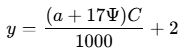
Chromaticity is bounded by International Commission on Illumination (CIE) polygon corner coordinates in Annex I Section 7 (White bounding coordinates spanning x 0.310–0.525, y 0.283–0.440; Green x 0.009–0.300, y 0.356–0.723; Red x 0.660–0.735, y 0.259–0.320; Yellow x 0.575–0.618, y 0.382–0.425)6. Minimum service luminous intensity in candelas (cd) is defined by the Annex I Section 8 formula6:

where  is luminous intensity in candelas under service conditions,
 is the threshold factor of 2 × 10⁻⁷ lux,
 is luminous range in nautical miles (NM), and
 is atmospheric transmissivity, specified as 0.8 (corresponding to ~13 NM meteorological visibility)6. Annex I Section 8 limits maximum luminous intensity to prevent undue glare and prohibits achieving glare control through variable dimmers6.
Vessel Length Band | Light Type | Rule 22 Min Range (NM) | Formula Intensity (cd) | Annex I Table Value (cd) |
|---|---|---|---|---|
≥50 m | Masthead light | 6 | 94.21 | 94 |
≥50 m | Sidelight, sternlight, towing, all-round (W/R/G/Y) | 3 | 12.06 | 12 |
20 m to <50 m | Masthead light | 5 | 52.34 | 52 |
12 m to <20 m | Masthead light | 3 | 12.06 | 12 |
12 m to <50 m | Sidelight, sternlight, towing, all-round | 2 | 4.29 | 4.3 |
<12 m | Masthead, sternlight, towing, all-round | 2 | 4.29 | 4.3 |
<12 m | Sidelight | 1 | 0.86 | 0.9 |
Towed inconspicuous / partly submerged object | White all-round light | 3 | 12.06 | 12 |
Sources: COLREG Rule 2231, Annex I Section 86, and exact formula evaluation at K = 0.844.
Spatial separation rules scale with vessel dimensions so multiple lights remain optically distinct at long range6. On vessels ≥20 m, the forward or single masthead light sits at a height above the uppermost continuous deck ("hull") of at least 6 m, or not less than the vessel’s breadth if breadth exceeds 6 m, capped at 12 m3. When two masthead lights are carried (mandatory at ≥50 m, optional under 50 m)11, their horizontal spacing must be at least half the vessel's length (not required to exceed 100 m), with the forward light placed within one-quarter of the vessel's length from the stem6. The after masthead light must be elevated at least 4.5 m vertically above the forward light so that under all normal trim conditions it appears clearly above and separate from the forward light at 1,000 m ahead of the stem when viewed from sea level6. Under Annex I Section 13, High-Speed Craft (HSC) may mount the masthead light lower relative to breadth if the end-elevation isosceles triangle formed with the sidelights maintains a base angle ≥27°, and HSC ≥50 m may adjust the 4.5 m vertical masthead separation to at least6:
where  is mainmast light height above the foremast light (m),
 is foremast light height above the waterline in service condition (m),
 is service trim (degrees), and
 is horizontal separation between masthead lights (m)6.
Spacing / Screening Requirement | Vessels ≥20 m | Vessels 12 m to <20 m | Vessels <12 m |
|---|---|---|---|
Forward masthead height | ≥6 m above hull (≥breadth if >6 m, max 12 m)6 | ≥2.5 m above gunwale6 | May be <2.5 m above gunwale; ≥1 m above sidelights6 |
After masthead elevation | ≥4.5 m above forward masthead (mandatory ≥50 m)6 | Optional; if fitted, ≥4.5 m above forward6 | Optional6 |
Sidelight placement & screens | ≤3/4 forward masthead height; not ahead of forward masthead; at/near ship side; mandatory matt-black inboard screens6 | ≤3/4 masthead height; if combined lantern, ≥1 m below masthead; matt-black screens if needed for Sec. 96 | Combined lantern allowed (<20 m); external screens unnecessary with narrow single-filament divider6 |
Vertical array spacing (2–3 lights) | ≥2 m apart (equally spaced); lowest ≥4 m above hull (towing excepted)6 | ≥1 m apart (equally spaced); lowest ≥2 m above gunwale (towing excepted)6 | ≥1 m apart; lowest ≥2 m above gunwale (towing excepted)6 |
Anchor lights (Rule 30) | When two carried, forward ≥4.5 m above aft; on vessels ≥50 m, forward ≥6 m above hull6 | When two carried, forward ≥4.5 m above aft6 | When two carried, forward ≥4.5 m above aft6 |
Sources: COLREG Annex I Sections 2, 3, 5, and 136.
Specialized installations follow additional geometric offsets. On fishing vessels, the lower of the two vertical all-round lights must sit at a height above the sidelights not less than twice the vertical spacing between those two lights, while direction-indicating gear lights sit 2–6 m horizontally clear of the red/white pair and vertically between the upper white light and the sidelights6. On dredgers and vessels engaged in underwater operations, obstruction and safe-pass lights must be positioned at the maximum practical horizontal distance—never less than 2 m—from the central Rule 27(b) vertical trio, with the upper offset light no higher than the lowest light of the trio6. Any vertical all-round array mounted between forward and after masthead lights must sit ≥2 m athwartships from the fore-and-aft centerline6. When fitted, a maneuvering light (Annex I Section 12) is mounted on the centerline plane at least 2 m vertically above the forward masthead light and ≥2 m vertically above or below the after masthead light (or ≥2 m vertically apart if only one masthead light is carried)6. Sidelight screens may form part of the ship’s structure and must follow manufacturer guidelines to avoid direct or reflected glare at watchkeeping stations1.
2. Navigation Light Control Panels & Redundancy
For ships of 50 m or more, IMO Resolution MSC.253(83) Section 4.1.3 specifies that masthead lights, sidelights, and sternlights be duplicated or fitted with duplicate lamps1. Vessels conventionally satisfy this using double-tier (duplex) luminaires—vertically stacked primary and reserve optical chambers (measuring ~490–535 mm tall in representative commercial double-tier fixtures)—or dual-source housings38. Legacy incandescent duplex lanterns employ shock- and vibration-resistant caged-filament lamps (such as 60 W or 65 W P28s bulbs operating at 24V DC, 110V AC, or 220V AC)39. Only manufacturer-specified lamps may be installed so unsuitable replacements do not degrade optical performance1.
Adopting multi-string and dual-power LED navigation lights introduces a failure mode absent in incandescent filaments. Whereas an incandescent filament fails as an abrupt open circuit that drops line current to zero, LED luminous intensity declines gradually over operating hours and temperature while electrical current draw remains constant1. As maritime industry technical analyses note, neither traditional nor modified current-sensing control panels detect an aging LED lantern whose output has slipped below COLREG minimums49. Consequently, MSC.253(83) Section 4.3 mandates one of two compliance paths for LED navigation lights1:
- Active Luminous-Intensity Alarm (Sec. 4.3.1): The luminaire or monitoring relay triggers a bridge alarm if luminous intensity falls below COLREG minimums due to aging or component degradation1. Modern addressable monitoring modules differentiate partial LED failure (blinking red alarm) from total failure (constant red alarm)29.
- Certified Service-Lifespan Control (Sec. 4.3.2): LEDs are operated strictly within a manufacturer-defined practical term of validity (commonly 50,000 hours in commercial designs), validated by thermal lumen-decay tests with a compliance margin and recorded on the type-approval certificate1. Some vendors implement temperature-compensated internal hour clocks or periodic drive-current boosts across 50,000 hours, though technical reviews observe that these Section 4.3.2 methods manage lifespan without directly measuring live light output49.
Modern solid-state lanterns house dual independent LED/power channels ("dual power LED") inside IP68 corrosion-resistant anodized aluminum or polycarbonate enclosures, with optional low-energy de-icing heaters rated in manufacturer cold-chamber testing down to -60°C2.
Under MSC.253(83) Section 6, every navigation light must connect via its own separate branch circuit with individual fault protection to the bridge Navigation Light Control Panel (NLC) so a short circuit or fault on one fixture cannot affect any other light (aside from dedicated canal signal circuits)1. Traditional bridge panels wired current-sensing relay coils in series with each light, ensuring any series visual indicator was shunted so indicator bulb failure could not open-circuit the navigation light; normally closed (NC) relay contacts closed on current drop to trigger the audible buzzer48. Representative modular NLCs (such as Den Haan Rotterdam NLS 3000, Lopolight NLC, Inelteh, Böning AHD-DPS02, and Haixing HX-NLC) monitor up to 42–48 circuits via microprocessor channels20. For example, the NLS 3000 pairs two-pole 5×20 mm fuse protection with dual-range current sensing per channel—a shunt sensor for low-current LED loads up to ~200 mA and a Hall sensor up to ~4 A—digitized by a 10-bit ADC over an internal FMS bus20, while Lopolight LMR/Q relays enforce electronic over-current shutoff above 2 A with automatic 30-second reset retries29. Under MSC.253(83) Section 5, ships ≥50 m require logical graphic mimic status per Resolution MSC.191(79), dimmable indicators and screens to preserve bridge night vision, manual emergency bypass switches independent of controller electronics, and bi-directional standardized serial interfaces (IEC 61162 / NMEA 0183 over RS485 or CAN) to transmit alarms to the VDR and external bridge alarm systems and receive acknowledgements1.
Electrical supply fallback is governed by SOLAS Chapter II-1 Regulations 42 and 4317. Upon loss of main shipboard power, the emergency power source—situated above the uppermost continuous deck and outside main machinery spaces—must sustain COLREG navigation lights for at least 36 hours on passenger ships and 18 hours on cargo ships17. An emergency diesel generator (using fuel with closed-cup flashpoint ≥43°C) must auto-start and take load within 45 seconds of blackout, while an emergency accumulator battery (holding terminal voltage within ±12% of nominal) bridges the blackout gap instantaneously and supports at least 30 minutes of transitional emergency lighting and signaling17. Vessels may feed upper mast lights at 220/230V AC and lower lights at 24V DC from battery/converter buses19, or route dual AC/DC feeds into NLCs equipped with automatic changeover20. Copper conductor voltage-drop calculations (assuming copper resistivity ρ = 0.0175 Ω·mm²/m, two-way loop resistance R = 2ρL/A, resistive load current approximation I = P/V, and ΔV = I × R) demonstrate why LED retrofits mitigate low-voltage DC losses44:
- At 24V DC feeding a 65 W incandescent bulb (2.71 A) over a 100 m one-way mast run (200 m loop) in 1.5 mm² copper (R = 2.33 Ω), voltage drop reaches 6.32 V (26.33%), severely under-volting the lamp; even over 60 m in 2.5 mm² copper (R = 0.84 Ω), drop is 2.28 V (9.48%)44.
- Replacing the bulb with a 15 W LED at 24V DC (0.625 A) reduces the 60 m drop to 0.88 V (3.65%) in 1.5 mm² or 0.53 V (2.19%) in 2.5 mm², whereas 230V AC keeps a 65 W load over 100 m in 1.5 mm² to 0.66 V (0.29%)44.
3. Ship’s Whistle / Tyfon & Acoustic Physics (COLREG Part D & Annex III)
COLREG Rule 33 and Annex III specify acoustic signaling appliances—whistles, bells, and gongs—to guarantee minimum propagation ranges while limiting bridge and deck noise exposure10. Commercial vessels primarily install compressed-air diaphragm tyfons or electrically driven piston horns, alongside electronic quartz-oscillator amplifier systems on specialized installations22.
In a compressed-air diaphragm tyfon (such as Kockum Sonics Supertyfon or Zöllner Makrofon), pressurized air acts behind a thin metallic diaphragm seated against an acoustic exhaust nozzle22. Air pressure deflects the diaphragm and escapes into a tuned exponential horn, driving self-sustained acoustic oscillation22. Vendor specifications cover 6–30 bar via exchangeable choke flanges on Supertyfon AT 150/165 units (consuming 25–35 L/s, weighing ~14 kg, producing 148 dB total / 138 dB 1/3-octave SPL)24 and 7–40 bar on Makrofon M125 units22. Zöllner technical documentation notes that pneumatic diaphragm horns generate a broad harmonic spectrum that helps listeners perceive the fundamental pitch via "residual tone" reconstruction even when engine or wind noise masks the fundamental frequency22. Actuation redundancy in valve blocks (e.g., Valve Unit TV 784) pairs dual pilot solenoids (normal and emergency coils, 8–27 W) with an independent mechanical wire pull-lanyard22.
Electric piston horns (such as Zöllner ZET-Horn and Kockum Sonics Electro-Tyfon MT/MTX 150) eliminate masthead air piping and condensate maintenance25. A 3-phase AC motor (230V, 380V, 440V, or 690V at 50/60 Hz, 5.5–22 A) drives a reciprocating piston via crankshaft and grease-lubricated gears (ZET-Horn) or an oil-free swinging piston inside an unlubricated cylinder (Electro-Tyfon)25. ZET-Horns reach full acoustic output in under 0.15 seconds59, while Electro-Tyfon units match motor speed to horn acoustic resonance across temperature and mains voltage/frequency variations and utilize rectangular front outlets to reduce downward deck noise by 6–8 dB—at a masthead mass of ~68 kg for an MT 150/13025. Where electronic whistle or bell/gong systems are installed, quartz-crystal-stabilized amplifiers drive marine acoustic emitters23; detailed acoustic parameters for small membrane-type marine horns were not present in the retrieved maritime manufacturer datasheets.
Characteristic | Compressed-Air Diaphragm Tyfon | Electric Piston Horn |
|---|---|---|
Drive source | 6–40 bar compressed air + 24V DC / 230V AC pilot valve + manual lanyard22 | 3-phase AC motor (230/380/440/690V, 50/60 Hz; 5.5–22 A)26 |
Sound mechanism | Air-excited oscillating metal diaphragm against nozzle seat24 | Crank/gear reciprocating or oil-free swinging piston in cylinder25 |
Acoustic & deck-noise profile | Rich harmonic overtones supporting residual-tone perception22 | <0.15 s run-up59; rectangular horn option cuts deck SPL by 6–8 dB25 |
Cold-climate protection | Thermostatic electric valve heater (e.g., 24–25 W) and mast-foot condensate drain filter23 | Motor-winding anti-condensation heating, vertically self-draining cylinder, thermal resonance matching25 |
Mass & upkeep | Light (~14 kg for 75–200 m class); monthly air-filter draining24 | Heavy (~68 kg for 75–200 m class); no air lines; periodic piston-ring wear checks26 |
Sources: Kockum Sonics / Venteville and Zöllner marine manuals22.
Annex III Section 1 assigns fundamental whistle frequencies inversely with vessel length within an overall 70–700 Hz band so deep pitches identify large ships while smaller craft emit higher frequencies24. In air at 20°C (c = 343 m/s), acoustic wavelengths span 4.90 m at 70 Hz, 2.64 m at 130 Hz, 1.72 m at 200 Hz, 1.37 m at 250 Hz, 0.98 m at 350 Hz, and 0.49 m at 700 Hz, contracting slightly in polar air at -20°C (c = 319 m/s) to 4.56 m at 70 Hz and 0.46 m at 700 Hz44. Annex III evaluates minimum 1/3-octave-band sound pressure levels (referenced to 2 × 10⁻⁵ N/m²) within 180–700 Hz (±1%) for vessels ≥20 m and 180–2100 Hz (±1%) for vessels <20 m32. Note that IMO Resolution A.910(22) (in force 29 November 2003) raised the <20 m minimum in the 800–2100 Hz band from 110 dB to 111 dB32.
Vessel Length Band | Fundamental Frequency (Hz) | Evaluation Band (Hz) | Min 1/3-Octave SPL at 1 m (dB) | Approx. Range (NM) | Bell & Gong Requirement (Rule 33) |
|---|---|---|---|---|---|
≥200 m | 70–200 | 180–700 (±1%) | 143 | 2.0 | Bell (≥300 mm, fwd) + Gong (aft), ≥110 dB @ 1 m33 |
100 m to <200 m | 130–350 | 180–700 (±1%) | 138 | 1.5 | Bell (≥300 mm, fwd) + Gong (aft), ≥110 dB @ 1 m33 |
75 m to <100 m | 130–350 | 180–700 (±1%) | 138 | 1.5 | Bell (≥300 mm, fwd), ≥110 dB @ 1 m33 |
20 m to <75 m | 250–700 | 180–700 (±1%) | 130 | 1.0 | Bell (≥300 mm, fwd), ≥110 dB @ 1 m33 |
12 m to <20 m | 250–700 | 180–2100 (±1%) | 120 (180–450 Hz) / 115 (450–800 Hz) / 111 (800–2100 Hz) | 0.5 | Whistle mandatory; bell/gong not required10 |
<12 m | Exempt (efficient sound means) | — | — | — | Some efficient means of making sound required10 |
Sources: COLREG Rule 33 and Annex III10. Approx. audibility ranges represent ~90% probability in still air with average background noise33.
To limit acoustic blind zones and prevent crew hearing injury, Annex III regulates radiation patterns and whistle placement33. Directional whistles must stay within 4 dB of maximum SPL across ±45° and within 10 dB in all other horizontal directions (preserving ≥50% forward range in any direction), and if installed as the ship’s sole whistle must aim straight ahead33. Whistles must be mounted as high as practicable so own-ship sound levels at listening posts (bridge wings and forecastle head58) never exceed 110 dB(A) and preferably stay ≤100 dB(A)33. Where cargo gear or superstructures block sound, vessels may install a combined whistle system—multiple whistles spaced ≤100 m apart, sounded simultaneously, with fundamental frequencies differing by at least 10 Hz—which counts legally as one whistle32. Whistles spaced >100 m apart must not sound simultaneously and do not require distinct frequencies33.
For sub-zero and polar service, pneumatic tyfons incorporate thermostatic electric valve heaters (e.g., 24–25 W in TV 784 units23, energized via bridge fog-signal panels28) plus primary mast-foot condensate filters on air runs longer than 100 m24. Electric piston horns rely on motor-winding anti-condensation heating (e.g., via Kockum Sonics TK 80/TK90A contactors), vertically suspended self-draining cylinders, and automatic thermal resonance matching25.
Under Rule 33 and Annex III Section 2, vessels ≥20 m must carry a corrosion-resistant forward bell with mouth diameter ≥300 mm and striker mass ≥3% of bell mass32. Vessels ≥100 m must carry an additional aft gong whose tone cannot be confused with the bell10. Both bell and gong must generate ≥110 dB at 1 m; power-driven strikers or electronic acoustic equivalents (such as the Kockum Sonics BG 300 24V DC, 2×120 W amplifier driving -30°C to +60°C emitters) are permitted provided manual sounding remains possible10.
4. Day Shapes & Hoisting Arrangements
From sunrise to sunset, COLREG Part C (Rules 20–31) requires matte black day shapes silhouetted against daylight sky2. For vessels ≥20 m, Annex I Section 6 standardizes four geometric primitives6:
- Ball: Spherical shape with diameter ≥0.6 m6.
- Cone: Base diameter ≥0.6 m and height equal to base diameter (≥0.6 m); two cones placed apex-to-apex form the vertical hourglass fishing signal6.
- Diamond: Two ≥0.6 m cones joined at a common base (1.2 m combined height)6.
- Cylinder: Diameter ≥0.6 m and height twice its diameter (≥1.2 m)6.
When shapes are displayed in a vertical line, Annex I Section 6(b) mandates a vertical spacing of at least 1.5 m between shapes6. Vessels <20 m may use smaller shapes commensurate with vessel size with correspondingly reduced spacing6.
COLREG Part C and Annex I govern functional hoisting positions rather than mechanical halyard hardware (cordage, blocks, or folding frames): shapes must be rigged "where they can best be seen"—typically on foremast heads, fore yardarms, or forward stays clear of deck obstructions7. Under Annex I Section 4(b), dredgers and underwater-operations vessels exhibiting side-specific obstruction and safe-pass shapes must hoist them at the maximum practical horizontal distance (≥2 m) from the central RAM vertical trio, with the upper side shape no higher than the lowest central shape6. Small diving vessels unable to rig full RAM shapes display a rigid replica of International Code Flag "A" at least 1 m high arranged for 360° visibility7. In towing operations, the 200 m threshold triggering diamond shapes on both tug and tow is measured from the stern of the towing vessel to the after end of the tow rather than towline length alone7. National modifications also apply—for example, Canadian Modification Rule 28(b) omits Constrained by Draught signals in Canadian waters and makes the motor-sailing cone optional under 12 m8.
Vessel Status / Constraint | COLREG Rule | Day Shape Configuration | Applicability & Positioning Notes |
|---|---|---|---|
Not Under Command (NUC) | Rule 27(a)(ii) | 2 Balls in vertical line (≥1.5 m apart)6 | Secondary summaries note exemption for vessels <12 m69 |
Restricted in Ability to Manoeuvre (RAM) | Rule 27(b)(ii) | Ball – Diamond – Ball in vertical line7 | Secondary summaries note exemption <12 m except dive vessels69 |
RAM (Dredging / Underwater Ops with obstruction) | Rule 27(d)(ii) | Central Ball–Diamond–Ball + 2 Balls (obstructed side) + 2 Diamonds (clear side), offset ≥2 m horizontally6 | Small dive boats may display rigid Flag "A" (≥1 m, all-round visible)7 |
Mineclearance Operations | Rule 27(f) | 3 Balls (1 near foremast head, 1 at each fore yardarm)7 | Indicates danger within 1,000 m7 |
Constrained by Draught (CBD) | Rule 28 | 1 Cylinder7 | Omitted in Canadian waters under Canadian Rule 28(b)8 |
At Anchor | Rule 30(a)(i) | 1 Ball (in forepart)7 | Secondary summaries note exemption <7 m outside fairways69 |
Aground | Rule 30(d)(ii) | 3 Balls in vertical line7 | Secondary summaries note exemption <12 m69 |
Towing (length of tow >200 m) | Rule 24(a)(v), (e)(iii) | 1 Diamond on towing vessel + 1 Diamond on towed vessel/object7 | No day diamond required if tow ≤200 m3 |
Engaged in Fishing | Rule 26(b)(i), (c)(i)–(ii) | 2 Cones apex-to-apex (vertical); + 1 Cone apex-up toward gear if gear extends >150 m7 | Exhibited whether underway or at anchor; Annex I allows <20 m size scaling6 |
Sailing vessel propelled by machinery | Rule 25(e) | 1 Cone, apex downwards (forward)7 | Optional <12 m under Canadian modification8 |
Sources: COLREG Part C Rules 24–30 and Annex I6.
5. Operational Signals & Common Faults
COLREG Part D (Rule 32) defines a short blast as lasting about 1 second and a prolonged blast as 4 to 6 seconds70. Rule 34 governs vessels in sight (plus obscured bends), permitting power-driven vessels to supplement whistle blasts with a synchronized all-round white light visible at ≥5 NM using ~1-second flashes separated by ~1-second gaps, with ≥10 seconds between successive signals15. On ships whose whistles are >100 m apart, only one whistle may be sounded for Rule 34 signals14. Rule 35 prescribes continuous periodic signals in or near restricted visibility4.
Rule / Regime | Operational Situation | Prescribed Signal Pattern | Timing & Operational Rules |
|---|---|---|---|
Rule 34(a)–(b) (In sight) | Alter starboard / Alter port / Operating astern propulsion | 1 short (stbd) / 2 short (port) / 3 short (astern propulsion)5 | Optional 1, 2, or 3 white flashes; 3 short denotes astern propulsion, not stationary vessel14 |
Rule 34(c) / Rule 9(e) (Narrow channel) | Overtake on starboard / port / Overtaken agreement | 2 prolonged + 1 short (stbd) / 2 prolonged + 2 short (port) / 1 prolonged, 1 short, 1 prolonged, 1 short (agreement)5 | Used only when vessel being overtaken must act to permit safe passing5 |
Rule 34(d) (Warning) | Doubt of other vessel's intentions or action | ≥5 short rapid blasts (may supplement with ≥5 short rapid flashes)5 | Sounded immediately upon doubt5 |
Rule 34(e) (Blind bend) | Nearing obscured bend / obstruction | 1 prolonged blast; answered with 1 prolonged blast5 | Applies where intervening terrain hides approaching traffic5 |
Rule 35(a)–(b) (Fog) | Power-driven making way / underway but stopped | 1 prolonged (making way) / 2 prolonged ~2 s apart (no way)4 | Interval ≤2 minutes4 |
Rule 35(c)–(d) (Fog) | NUC, RAM, CBD, Sailing, Fishing (incl. at anchor), Towing/Pushing | 1 prolonged + 2 short blasts4 | Interval ≤2 minutes4 |
Rule 35(e) (Fog) | Vessel towed (or manned last vessel of tow) | 1 prolonged + 3 short blasts4 | Interval ≤2 minutes, immediately after towing vessel if practicable4 |
Rule 35(g)–(h) (Fog) | At anchor / Aground | Anchor: rapid bell ~5 s (+ rapid gong ~5 s aft if ≥100 m); Aground: 3 distinct bell strokes before and after anchor bell/gong signal4 | Interval ≤1 minute; anchor may add short–prolonged–short whistle; aground may add appropriate whistle4 |
Rule 35(k) (Pilotage) | Pilot vessel on pilotage duty | Identity signal: 4 short blasts4 | In addition to 35(a), (b), or (g) signals4 |
Rule 35(i)–(j) (Small craft) | 12–<20 m (exempt from bell) / <12 m (exempt above) | Efficient sound signal if prescribed signals omitted4 | Interval ≤2 minutes4 |
Sources: COLREG Rules 32, 34, and 354.
For general attention under Rule 36, vessels may use unambiguous light or sound signals or aim a searchlight toward a danger without embarrassing other vessels10. Annex IV (rewritten in 200778) restricts Distress Signals strictly to emergencies requiring assistance16; documented Annex IV signals include continuous sounding of any fog-signaling apparatus, gun or explosive shots at ~1-minute intervals, red-star rockets/shells, red parachute flares, hand flares, orange smoke, flames on deck, International Code flags "NC", a square flag with a ball above or below it, slowly raising and lowering outstretched arms, and Digital Selective Calling (DSC) distress alerts9.
In operational service, signaling hardware experiences recurring degradation modes that drive Port State Control (PSC) inspection findings (an industry compliance blog summary cites 136 detainable safety-of-navigation deficiencies alongside 119 water/weathertight defects)79:
- Water Ingress, Gasket Failure & Electrical Corrosion: Exposed deck and masthead housings face continuous spray, condensation, and thermal cycling81. Documented vessel electrical casualty service reports (e.g., MT AEPCO) identify forward masthead short circuits from water ingress and corroded plug connections, wet and rusted signal-light holders, failed NLC control relays, blown branch fuses, tripped 24V DC battery-charger breakers, and incorrect colored lenses installed during repairs19.
- LED Driver Stress & Undetected Optical Decay: Supply voltage swings, vibration, and thermal stress shorten LED driver life and accelerate lumen depreciation50. Because LED current draw stays flat as light output fades, legacy current-monitoring relays cannot alert watchkeepers to dim fixtures unless active intensity-failure alarms or strict 50,000-hour lifecycle tracking are implemented49.
- Frozen or Fouled Pneumatic Tyfon Lines: Un-drained air pipelines longer than 100 m carry water condensate and rust scale into valve bodies and horn seats if primary mast-foot filters are not drained monthly24. Dirt or seat wear between the diaphragm and nozzle distorts or silences output24, while sub-zero moisture freezes unheated pilot valves and sticking pistons, delaying activation until thawed or freed24.
- Electric Horn & Blackout-Changeover Faults: Rigid cabling at electric horn motors fails from start/stop vibration unless flexible leads are installed26, and uninspected piston horns risk cylinder scoring or piston-ring wear below the 5.5 mm replacement limit64. At the power distribution layer, Tokyo MOU PSC inspections have recorded vessels whose emergency generators passed "simulated blackout" tests yet failed to supply essential loads—including navigation lights—under SOLAS Chapter II-1 Regulations 42–43 during an actual blackout84.
References
- RESOLUTION MSC.253(83) (adopted on 8 October 2007, https://wwwcdn.imo.org/localresources/en/KnowledgeCentre/IndexofIMOResolutions/MSCResolutions/MSC.253(83).pdf
- Understanding SOLAS Regulations for Marine Navigation Lights, https://www.yushuolighting.com/understanding-solas-regulations-for-marine-navigation-lights
- ColRegs – Lights, Shapes, Sound and Light Signals - Bluewater Miles, https://bluewatermiles.com/docs/colregs-lights-and-shapes.pdf
- COLREG Rule 35: Fog Signals Explained - ialacolreg, https://ialacolreg.com/en/colreg/rule-35
- Rule 34: Vessel Maneuvering Signals | PDF | Transport - Scribd, https://www.scribd.com/document/291078238/Rule-34-Manoeuvring
- Annex I COLREGs: Positioning and details of lights and shapes, https://app.lanternakonsult.se/about/colregs/annex-i-positioning-and-technical-details-of-lights-and-shapes/
- COLREGs Day Shapes Explained: Meanings and Rules - StandOn, https://getstandon.com/resources/day-shapes
- COLREGS Part C Day Shapes - OpAnalytics, https://opanalytics.ca/courses/mod/page/view.php?id=12
- COLREG - Preventing collisions at sea, https://www.imo.org/en/ourwork/safety/pages/preventing-collisions.aspx
- Sound and Light Signals in COLREGs | PDF | Maritime Pilot - Scribd, https://www.scribd.com/document/898883117/Colregs-Mid
- 01 COLREG Convention on the international regulations for, https://puc.overheid.nl/nsi/doc/PUC_2381_14/1/
- Regulations of 1 December 1975 No. 5 for preventing collisions at, https://www.sdir.no/siteassets/engelske-forskrifter-pdf/1-december-1975-no.-5-rules-of-the-road-at-sea2.pdf
- COLREG-Consolidated-2018.pdf, https://www.samgongustofa.is/media/log-og-reglur/COLREG-Consolidated-2018.pdf
- COLREGs course - Rule 34 (Manoeuvring and warning signals), https://ecolregs.com/index.php?option=com_k2&view=item&layout=item&id=66&Itemid=406&lang=en
- COLREG Rule 34: Blasts and Warning Signals - ialacolreg, https://ialacolreg.com/en/colreg/rule-34
- MARITIME DISTRESS SIGNALS (Annex IV to the Rules), https://fernhurstbooks.com/_userfiles/pages/files/additional_rescorces/learn_the_nautical_rules_of_the_road/distress_signals_c10.pdf
- SOLAS Ch. II-1 Reg. 42 - Emergency source of electrical power, https://www.imorules.com/GUID-C048F800-5412-40B3-ACCD-C562D4E4F719.html
- SOLAS Ch. II-1 Reg. 43 - Emergency source of electrical power, https://www.imorules.com/GUID-7F31AD5F-EA75-4FB7-AFA1-04BCEFA9462B.html
- Navigation Light System Repair Report - MT AEPCO - Scribd, https://www.scribd.com/document/947105581/S25004-Navigation-Light-MT-AEPCO
- NLS 3000 Control Panel - TECHNICAL MANUAL, https://www.dhr.nl/sites/default/files/userfiles/Producten/Navigatie/Downloads/Technical%20Manual%20NLS3000%20NLC-System.pdf
- Navigation panels for Navigation Lighting | Inelteh Marine, https://www.inelteh.nl/en/navigation-panels/
- Made by ZÖLLNER The Sound of Excellence Makrofon • ZET-Horn, https://www.pacatlantic.com/zollner/wp-content/uploads/sites/3/2015/06/Yacht-Horn-Brochure.pdf
- Ship Whistle & Gong System Guide | PDF | Thermostat | Valve - Scribd, https://www.scribd.com/document/742770760/AD0039-FD
- SUPERTYFON - Venteville, https://www.venteville.com/wp-content/uploads/2020/05/MANUAL-AT150-165-TV784-VV.pdf
- Kockum Sonics MTX 150 130 | PDF | Piston - Scribd, https://www.scribd.com/document/754942758/Kockum-Sonics-MTX-150-130
- ELECTRO–TYFON MT 150/130 - Venteville, https://www.venteville.com/wp-content/uploads/2020/05/MANUAL-MT150-130-TK80-VV.pdf
- Kahlenberg M-485A fog signal timer, https://kahlenberg.co.uk/m-485a-sound-signal-controller/
- Fog Horn Controller WZK, https://bochimarine.com/10-6-19-fog-horn-controller.html
- Navigation Light Controller (NLC) - Lopolight, https://lopolight.com/Files/Files/Downloads/Manualer/NLC%20manual%20rev%207.4%20Jan%202025%20Ships.pdf
- Navigation lights controller - Haixing Maritime Electric Group, https://en.haixing.com/products/Ship_and_offshore_lighting/Navigation_sig/2024/0621/16.html
- Rule 22 Visibility of lights - imorules, https://www.imorules.com/GUID-668718FF-AC6A-4037-8F70-2BFF63467EF2.html
- ANNEX III - Technical Details of Sound Signal Appliances - Cult of Sea, https://www.cultofsea.com/colregs/annexes/annex-iii-technical-details-of-sound-signal-appliances/
- COLREGs Annex III: whistle, bell and gong specs - Shimbiri, https://shimbiri.ai/colregs/annex-iii
- Technical Information - Text Version - | ClassNK - English, https://www.classnk.or.jp/hp/en/tech_info/tech_text.aspx?techno=760
- Notice on the Use of LED Navigation Lights on Ships, https://www.ccs.org.cn/ccsewwms2007/displayFileInfo.do?project=wms&file=8a81851c97f8ba4c019c30e973ad00a8&name=/wms/Notice+on+the+Use+of+LED+Navigation+Lights+on+Ships1770347131820.pdf
- COLREG Rules 1–41: Explained with Free Practice - ialacolreg, https://ialacolreg.com/en/colreg
- Annex I: Ship Lights & Shapes Details | PDF | Mast (Sailing) - Scribd, https://www.scribd.com/presentation/510132534/Annex-I-sections-1-3
- beetee polycarbonate body double tier navigational lights irs approved, https://www.bharattradersindia.in/navigation-light.html
- Double navigation light - All boating and marine industry, https://www.nauticexpo.com/boat-manufacturer/double-navigation-light-47529.html
- S-01 NAVIGATION LIGHT, https://www.ccs.org.cn/ccswzen/file/download?fileid=201950000000002081
- Vessel Light Positioning Guidelines | PDF | Sound | Trawling - Scribd, https://www.scribd.com/doc/26570389/Rules-Annexes
- COLREGs course - Rule 22 (Visibility of lights), https://ecolregs.com/index.php?Itemid=395&lang=en
- COLREG Rule 22: Visibility of Lights by Length - ialacolreg, https://ialacolreg.com/en/colreg/rule-22
- unknown_url
- International Regulations for Preventing Collisions at Sea PART E, https://econadin.com/en/international-regulations-for-preventing-collisions-at-sea-part-e/
- Masthead Navigation Light clear Double. Vessels >50m Unilux, https://www.galanos.gr/product/masthead-navigation-light-clear-double-vessels-50m-unilux/
- Duplex navigation lights | Den Haan Rotterdam Netherlands, https://www.dhr.nl/dhr-marine/blogs/duplex-navigation-lights
- Navigation and Signal Lights, https://studfile.net/preview/5648164/page:2/
- Transitioning to LED Navigation Lights - Signal Mate, https://signalmate.com/wp-content/uploads/2019/06/Marine-News-June-2019.pdf
- SAFETY: Transitioning To LED Navigation Lights - MarineLink, https://www.marinelink.com/news/safety-transitioning-led-navigation-467745
- DATASHEET - Navigatieverlichting Lopolight, https://navigatieverlichting.com/wp-content/uploads/2021/10/201-005-Datasheet-VV-1.pdf
- THE ULTIMATE NAVIGATION LIGHT SOLUTION - Lopolight, https://lopolight.com/Files/Files/Downloads/Brochures/SuperYacht_Catalog_700-907_Web.pdf
- Navigation Light Control and Monitoring - Böning, https://www.boening.com/en-gb/product-categories/positionslaternen-ueberwachung
- NLS 3000 Navigation Light Control Manual | PDF - Scribd, https://www.scribd.com/document/890541531/nls-3000-b
- SOLAS Chapter II-1: Machinery Standards | PDF | Ships - Scribd, https://www.scribd.com/document/898400171/Solas-Ielts-Chp-II-C-g
- SOLAS Emergency Generator Requirements | PDF - Scribd, https://www.scribd.com/document/904684847/Em-cy-GE-solas
- Navigation panels - Electronic Devices, http://www.electronic-devices.co.uk/nav_panels.php
- 1.....directive-8-2017-colreg.pdf, https://dma.gov.mm/wp-content/uploads/2017/02/1.....directive-8-2017-colreg.pdf
- ZET-Horn Overview - ZÖLLNER Signal GmbH, https://www.zoellner.de/en/marine/zet-horn-overview
- Electronic Whistle ETD 100/350 with Power Amplifier MTK 250 incl, https://www.marinsupply.no/media/multicase/documents/datablad/ksm819e-2445-amplifier_mtk250_incl_triotone_hi.pdf
- tyfon_type_t75bc_no.607.pdf - Berio Molina, https://beriomolina.com/wp-content/uploads/2018/05/tyfon_type_t75bc_no.607.pdf
- ZET-HORN 70AC - Nortelco, https://www.nortelco.no/no/Catalogues-Zollner?iid=323895&pid=Nortelco-StackModules-LinkSectionModule-Links.Nortelco-LinkModuleLink-File
- Other audible signaling equipment for ships - NauticExpo, https://www.nauticexpo.com/cat/safety-equipment-clothing/other-audible-signaling-equipment-ships-RN-1479.html
- Tyfon Manual | PDF | Piston | Mains Electricity - Scribd, https://www.scribd.com/document/726262114/Tyfon-Manual
- Technical Information - ClassNK, https://www.classnk.or.jp/hp/pdf/tech_info/tech_img/t489e.pdf
- colregs.pdf - Good Hope Sailing Academy, https://www.goodhopesailingacademy.co.za/wp-content/uploads/2022/11/colregs.pdf
- Electro–Tyfon® MTX 150/120 - R. STAHL Tranberg, https://stahl-tranberg.com/wp-content/attachments/TPS7445.pdf
- A power-driven vessel towing, length of the tow over 200 m - shapes, https://ecolregs.com/index.php?option=com_k2&view=item&id=286:a-power-driven-vessel-towing-length-of-the-tow-over-200-m-shapes&Itemid=505&lang=en
- Day shapes - Wikipedia, https://en.wikipedia.org/wiki/Day_shapes
- Sound Signals - COLREG Simulator - SkipperCheck, https://skippercheck.net/colreg-simulator/sound-signals
- COLREGs Rule 34, Manoeuvring and Warning Signals - Shimbiri, https://shimbiri.ai/colregs/rule-34
- Navigation Rules - uscg navcen, https://navcen.uscg.gov/sites/default/files/pdf/navRules/navrules.pdf
- Rule 34: Manoeuvring And Warning Signals - Nautical Know How, https://nauticalknowhow.mysailingcourse.com/irpcs/rule-34/
- COLREGs Rule 34: Manoeuvring and warning signals - learntosail.io, https://learntosail.io/tools/colregs/rules/rule-34-manoeuvring-and-warning-signals
- A vessel intended to be overtaken in a narrow channel or fairway, https://ecolregs.com/index.php?option=com_k2&view=item&id=311:a-vessel-intended-to-be-overtaken-in-a-narrow-channel-or-fairway-does-not-agree-with-intention-of-overtaking-vessel&Itemid=505&lang=en
- COLREGs course - Rule 35 (Sound signals in restricted visibility), https://ecolregs.com/index.php?Itemid=304&id=67&lang=en&layout=item&option=com_k2&view=item
- COLREGs course - Rule 35 (Sound signals in restricted visibility), https://www.ecolregs.com/index.php?Itemid=407&id=67&lang=en&option=com_k2&view=item
- Rules of the road, https://cdn.prod.website-files.com/68278fdd0d3a6348cbd1616b/683061e5162872f6ab6c47a2_5555047790.pdf
- PSC Deficiencies: Life-Saving Appliances Prevention Guide, https://marineinspection.app/blog/psc-common-deficiencies-lifesaving-appliances-prevention
- Frequent Deficiencies per PSC Authority - Dromon Bureau of Shipping, https://www.dromon.com/wp-content/uploads/2018/06/C17024-Frequent-deficiencies-per-PSC-Authority.pdf
- IEC 60945 for Marine Navigation Lights: How to Ensure Compliance, https://www.yushuolighting.com/iec-60945-for-marine-navigation-lights
- Testing and Certification for Navigation Lights and Marine ... - Intertek, https://www.intertek.com/lighting/transportation/navigation-and-marine/
- Understanding Marine Navigation Light Requirements for Vessel, https://sealight.no/blogs/maritime-insights/understanding-marine-navigation-light-requirements-for-vessel-safety
- Emergency Power Supply Testing from Tokyo MoU | Marine & Offshore, https://marine-offshore.bureauveritas.com/newsroom/emergency-power-supply-testing-tokyo-mou