Part 1: System cardDel 1: Systemkort
Core Function
Shipboard mooring systems restrain a vessel alongside a berth or terminal against wind, current, swell, passing-ship dynamic loads, and ship-to-berth height differences1. High-tensile steel-wire or synthetic lines lead from powered winch drums or fixed bollards through hull-mounted chocks and fairleads to shore points5. Winches haul lines into position and transfer restraint onto calibrated mechanical brakes or constant-tension control loops, while fairleads and elastic synthetic tails redirect forces into the reinforced hull structure and damp shock loads within safe working limits1.
Primary Operational Tasks
- Line Heaving and Payout: Hauling, paying out, and storing mooring lines on powered drums (typically rated at 20–33% of Ship Design Minimum Breaking Load, MBL_SD, on the first layer) to position and secure the vessel1.
- Mechanical Brake Holding: Securing berthed lines statically on band or disc brakes calibrated to hold 60% of MBL_SD on the first drum layer while permitting controlled slip under overload7.
- Automatic Constant-Tension Adjustment: Modulating winch motor speed and torque in closed-loop constant-tension mode to maintain target line load and restrain vessel motion automatically8.
- Fairlead Load Redirection: Guiding lines across universal roller fairleads, pedestal rollers, and closed chocks at controlled bend radii to reduce chafe and transfer forces into hull frames6.
- Auxiliary Line Handling: Shifting lines between split-drum storage and tension sections through notched flanges, or working auxiliary lines on warping heads and capstans6.
System Interconnections
- Inputs: Hydraulic power from a vessel Hydraulic Power Unit (HPU) or AC/DC electrical supply through marine Variable Frequency Drives (VFDs)12; local and remote winch operator commands11; mechanical brake actuation via manual handwheel, spring pack, or hydraulic cylinder16; and real-time line-tension feedback from load cells or brake-anchor load pins17. Note that detailed hardware specifications for local deck pedestals, portable remote packs, or main switchboard breaker feeds are not covered in the available component literature11.
- Outputs: Controlled line hauling/holding tension8; calibrated brake rendering (controlled drum slip) under extreme surge overload7; and local plus Cargo Control Room (CCR) line-tension readouts to prevent unattended lines from becoming slack or over-tensioned13. Bridge-level mooring tension displays and automated brake-status alarms are not documented in the cited engineering standards13.
Redundancy & Criticality
Amended SOLAS Chapter II-1 Regulation 3-8 (IMO Resolution MSC.474(102), in force 1 January 2024) establishes binding design and lifecycle rules for towing and mooring equipment19. For new ships of 3,000 GT and above (contracts ≥ 1 January 2024, keels ≥ 1 July 2024, or deliveries ≥ 1 January 2027, extending to 2028 under specific structural criteria), arrangements and equipment must satisfy MSC.1/Circ.1175/Rev.1 and MSC.1/Circ.1619, while vessels under 3,000 GT comply as far as reasonably practicable21. On all ships with keels laid on or after 1 January 2007, bollards, bitts, fairleads, rollers, chocks, and winches must be clearly marked with safe operational limits (Safe Working Load, SWL ≤ MBL_SD) accounting for supporting hull attachment strength6. Retroactively from 1 January 2024, MSC.1/Circ.1620 requires all SOLAS vessels to maintain documented Mooring System and Line Management Plans (MSMP/LMP), periodic inspections, traceable test certificates, and replacement lines rated at 100–105% of MBL_SD20.
To preserve mechanical redundancy and prevent structural or line failure, OCIMF Mooring Equipment Guidelines Fourth Edition (MEG4, 2018) stipulate that a single winch motor should drive no more than two drums5. MEG4 enforces a weak-link brake hierarchy in which winch brakes are typically designed around 80% of MBL_SD—and must not exceed MBL_SD under MSC.1/Circ.1619—while operationally calibrated to render at 60% of MBL_SD on the first layer so the drum slips safely before the line (100–105% MBL_SD) or hull fittings reach failure7.
Part 2: Technical deep diveDel 2: Teknisk dybdeanalyse
Mooring Winch Designs & Auto-Tensioning
Shipboard mooring winches are categorized by drum geometry into undivided (conventional) drums and split-drum winches, trading mechanical simplicity against line preservation and holding consistency14. An undivided drum stores and tensions the entire mooring line on a single barrel9. Although it removes the need to shift rope between drum sections, multi-layer winding forces outer working turns under load to wedge and embed into softer underlying turns—a failure mode that crushes fibers and fouls payout, particularly on synthetic lines14. Multi-layer accumulation also increases the effective lever arm of the rope on the drum, reducing mechanical brake holding capacity and rated hauling pull as outer layers build up9. In addition, undivided drums are highly sensitive to fleet-angle alignment and rely on mechanical spooling gears that are prone to service damage28.
Split-drum winches solve both drawbacks by dividing the barrel with a notched separating flange—engineered with rounded slot edges to prevent line abrasion—into a wide multi-layer storage section and a narrow tension (working) section14. During normal mooring, unused line stays stowed loosely on the storage section while only the active working turns pass through the flange notch onto the tension drum in a single layer; OCIMF MEG4, ISGOTT, and ISO 3730 restrict loaded split-drum operation strictly to one working layer9. Industry and winch-maker design guidance recommends accommodating at least 10 turns on the tension section for steel wire rope and 5 to 6 turns for conventional fiber ropes to ensure friction grip without building a second layer28. Keeping the working line on the first layer preserves constant, maximum brake holding power and eliminates layer-to-layer line burying, though transferring lines across the flange notch introduces crew-handling and line-pinch hazards if ever attempted under tension14.
Design Attribute | Undivided (Conventional) Drum | Split-Drum Winch |
|---|---|---|
Drum Architecture | Single unified barrel for stowage and tension9 | Notched flange separating multi-layer storage and single-layer tension sections14 |
Working Layer Condition | Typically 3–4 layers under mooring load29 | Strictly 1 working layer on tension section (≥ 10 turns wire; 5–6 turns fiber)14 |
Brake Holding Consistency | Decreases as outer rope layers enlarge drum lever arm9 | Constant rated holding capacity calibrated to first-layer radius9 |
Line Burying / Pinch Risk | High; loaded outer turns bite into softer lower synthetic layers14 | Eliminated on tension drum; localized risk at flange slot if unrounded14 |
Crew Transfer Exposure | None; no section-to-section transfer needed27 | Present; shifting lines across flange slot risks injury if mismanaged14 |
Fleet-Angle & Spooling Sensitivity | High; misalignment damages line and mechanical spoolers28 | Moderate on storage side; fixed geometry on working drum9 |
Winch prime movers center on electro-hydraulic versus electric Variable Frequency Drive (VFD) powertrains12. Technical comparisons—drawn primarily from offshore equipment vendors and drive manufacturers rather than independent shipboard fleet trials—indicate that hydraulic winches powered by central or dedicated HPUs provide high torque output and sustain continuous heavy-duty cycles because circulating hydraulic oil acts directly as a heat-transfer medium15. Hydraulic drives also remain well-established for hazardous classified deck zones on tankers and gas carriers, albeit with lower overall efficiency from hydraulic conversion losses and higher ongoing maintenance for pumps, hoses, fluid cleanliness, and leak containment15. Conversely, electric VFD winches fed by three-phase AC shipboard power eliminate hydraulic oil systems, improve drive efficiency, integrate cleanly into digital vessel automation, and deliver smooth, continuous speed and torque regulation12. Their principal constraints are motor thermal management during prolonged full-load duty cycles and the higher capital cost of ATEX or equivalent explosion-proof certification in hazardous zones15.
Drive Characteristic | Electro-Hydraulic Drive (HPU) | Electric VFD Drive |
|---|---|---|
Power Supply | Pressurized oil via vessel HPU or dedicated hydraulic pack15 | AC/DC shipboard supply via marine Variable Frequency Drive12 |
Speed & Torque Control | Strong controllability via proportional valve architecture15 | Precise, repeatable continuous speed and torque regulation12 |
Continuous-Duty Thermal Handling | Well-established; hydraulic fluid transfers heat15 | Requires dedicated thermal management under sustained full load15 |
System Efficiency | Lower overall efficiency due to hydraulic conversion losses15 | Typically higher drive efficiency15 |
Hazardous Area Compliance | Well-established for classified marine deck zones15 | Requires ATEX/Ex certification, increasing cost and complexity15 |
Maintenance & Environment | Fluid checks, hose inspection, HPU servicing, leak control15 | Eliminates hydraulic oil handling; periodic motor/drive checks15 |
Automatic constant-tension (auto-tensioning) winches actively regulate line force without manual tending as berth elevation and environmental loads vary4. In closed-loop tension control, strain-gauge load cells or load pins fitted in the winch drum brake anchor measure line force and transmit signals to the drive controller17. When tension drifts outside a set deadband, the controller modulates motor torque  against external line load torque
 according to the rotational drum-drive dynamics34:
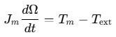
where  is the combined effective moment of inertia (motor, gearing, drum, and line) and
 is angular speed34. Winch control modeling (from offshore heave-compensation drawworks literature) demonstrates that on multi-layer drums, the effective transmission radius changes in discrete steps as the rope shifts layers, while overly aggressive proportional-integral (PI) gains or excessively short integration times can trigger torque oscillations and drive instability34. Because unattended lines can otherwise become slack or overloaded alongside, OCIMF MEG4 recommends fitting load sensors with dual readouts locally at the winch and in the CCR13. Operational procedures distinguish between running winches in auto-tension versus holding statically "on the brake"35; specific deadband percentages and terminal policies restricting auto-tension during liquid cargo transfer are not documented in the cited standards.
Winch Brake Holding Capacity & Rendering Physics
Mechanical band brakes—predominant on deck mooring winches, though disc brakes are noted in marine engineering literature as an alternative with advantages in operational consistency9—serve as the calibrated overload fuse of the mooring arrangement7. Under SOLAS II-1/3-8 and OCIMF MEG4, every component in the load path is sized around a single vessel-specific benchmark: the Ship Design Minimum Breaking Load (MBL_SD)7. For vessels with Equipment Number EN > 2,000, MSC.1/Circ.1175 defines baseline MBL_SD from side-projected windage area  (capped at 1,275 kN or 130 t where reduced wind-speed criteria apply, with acceptable wind speed not below 21 m/s against a 1.0 m/s design current)36:

Fitting oversized ropes stronger than MBL_SD without upgrading deck foundations shifts failure from an expendable line to hull-tearing bitts or winch pedestals1. Consequently, MSC.1/Circ.1619 requires mooring winches to have a brake holding capacity less than MBL_SD (or an adjustable brake)24. Standards vary slightly in their exact nominal ceilings: ISO 3730 specifies a minimum design Brake Holding Capacity (BHC) not less than 80% of line MBL on the first layer9, whereas Steamship Mutual, OCIMF MEG4 compliance guidance, and ClassNK summaries cite design brake capacities typically up to 80% of MBL_SD (capped ≤ MBL_SD under Circ.1619)7. Operationally, OCIMF MEG4, RightShip, and P&I clubs calibrate the brake to render (slip) at 60% of MBL_SD on the first drum layer (ClassNK also notes an ISO rendering benchmark of 50% MBL_SD)7. Setting the render point at 60% of MBL_SD preserves a safety margin of 40 percentage points below new line strength (LDBF = 100–105% of MBL_SD) and 15 percentage points below the mandatory 75% MBL_SD line-retirement threshold7.
System Element | Strength / Load Target (% of MBL_SD) | Governing Basis & Engineering Rationale |
|---|---|---|
Winch Hauling Pull (1st Layer) | 20–33% (22–33% ISO 3730)1 | Rated motor pull to heave lines alongside without overloading gear |
Normal Daily Mooring Load | ~20–25%1 | Industry operational guideline to minimize fatigue and extend line life |
Working Load Limit (WLL) | 50% (Synthetic) / 55% (Steel Wire)5 | Maximum operational working load limit under OCIMF MEG45 |
Operational Brake Rendering Load | 60% (OCIMF MEG4) / 50% (ISO summary)9 | Calibrated slip point acting as mechanical overload fuse on 1st layer7 |
Line Retirement Threshold | 75% residual strength38 | Mandatory discard threshold under OCIMF MEG4 and RightShip RISQ38 |
Design Brake Holding Capacity (BHC) | ~80% (≥ 80% ISO; capped ≤ 100% per Circ.1619)7 | Structural and friction design rating of brake band, drum, and linkage7 |
Line Design Break Force (LDBF) | 100–105% (new, dry, spliced)24 | Tested per ISO 2307 / CI 1500B; > 105% requires fitting/hull re-evaluation4 |
Tail Design Break Force (TDBF) | 125–130% (tested wet, MEG4)1 | Higher strength compensates for rapid cyclic wear at quay bollards5 |
Deck Fitting SWL | Spec > MBL_SD; Marked ≤ MBL_SD6 | Ensures fittings and hull seatings outlast single mooring lines6 |
Unlike OCIMF MEG4 practice—which makes tails stronger than main lines (125–130% MBL_SD) and depends on the 60% winch brake to prevent failure—some non-MEG4 vessels deliberately install slightly weaker tails so extreme overload breaks the inexpensive tail near the quay rather than snapping back the main line across deck1.
Physically, a locked band brake resists drum rotation up to a fixed resistive torque governed by band friction coefficient, wrap geometry, and actuator clamping force. During a hydraulic jack render test, the moment applied by the test jack ( at lever arm
 ) balances the mooring line moment (
 at effective drum radius
 ), which increases with drum layer
 for bare drum diameter
 and rope diameter
 29:

BHP Hay Point's 2024 terminal brake render guidelines demonstrate this layer sensitivity quantitatively29. On a winch with a 50 cm bare drum, 72 mm (7.2 cm) rope, 100 cm jack lever arm ( ), and 33.18 cm² jack piston area, calibrating the brake to render at 30 t on layer 3 (
 ) requires a test pressure of 380 bar (calculated as 12,900 kg / 33.18 cm² = 388 kg/cm²), generating 1,290,000 kg·cm of brake torque29. Yet that exact same brake torque applied on layer 1 (
 ) holds 45,104 kg (45 t)—a ~33% reduction in line holding capacity by layer 3—requiring verification that first-layer loading remains below the winch's 49 t maximum BHC29.
Periodic brake rendering tests must calculate target jack force from MBL_SD rather than the breaking load of whichever line is currently fitted7. Steamship Mutual and RightShip recommend testing at least annually (never stretching intervals to 5 years), as well as on newbuildings and immediately after lining renewal, band adjustment, drum resurfacing, linkage repair, unexpected premature slip, or changing to a different line diameter (like-for-like line replacements do not trigger retesting per RightShip)7. A typical maker-kit brake test proceeds sequentially7:
- Permit and Risk Control: Issue a work permit and risk assessment, clear deck snap-back paths, and verify calibration of the maker-supplied hydraulic jacking kit and gauges7.
- Pre-Test Mechanical Inspection: Check brake lining thickness against maker wear limits, inspect for glazing, oil contamination, or loose rivets, verify drum surface smoothness, check pins and linkages, and confirm correct rope reeling direction7.
- Target Moment Calculation: Compute required hydraulic jack pressure from 60% MBL_SD and exact drum geometry using layer 1 for split drums or the normal working layer (3–4) for undivided drums while checking the layer-1 BHC limit7.
- Brake Application and Hold-Back: Engage the brake exactly as in service (noting handwheel torque or spring compression) and load steadily; operational test-guidance manuals specify holding 100% target render load for 2 minutes with zero drum creep7.
- Dynamic Render Point Check: Increase jack pressure gradually (in 2–5% steps per operational test guidance) until the drum slips smoothly within acceptable limits (typically ±5% of target BRL in test-guidance manuals); "holding is not passing" because an over-tight brake turns the mooring line into the weak link7.
- Calibration Marking and Logging: Mark the verified handwheel torque or spring setting, stencil the test date, force, and percentage of MBL_SD onto the winch, and archive findings and photos in the MSMP brake log7.
Mooring Lines: Steel Wire, Synthetic & HMPE
Mooring line selection balances axial modulus, energy absorption, specific gravity, thermal limits, and bending fatigue39. Traditional steel wire ropes—typically 6×36 Warrington Seale with Independent Wire Rope Core (6×36 WS + IWRC) in 1,770–2,160 N/mm² galvanized wire (OCIMF MEG4 recommends minimum 38 mm 6×36 class, noting IWRC wire tensile ranges of 1,180–2,160 N/mm²)—elongate only ~1% under working load3. While steel wire excels in high-heat exposure and edge abrasion resistance42, it weighs 7 to 8 times as much as equivalent-strength HMPE, sinks, resists coiling, corrodes without continuous lubrication39, and suffers hidden internal wire fractures inside the IWRC under cyclic bending over sheaves—damage demonstrated in 2025 rope-fatigue laboratory testing to be invisible to routine exterior inspection45. Because steel wire has negligible elasticity to absorb dynamic surge, vessels using wire must fit high-elongation synthetic stretcher tails (sized at 125–130% MBL_SD wet TDBF under MEG4)1.
High-Modulus Polyethylene (HMPE)—ultra-high-molecular-weight polyethylene (UHMWPE) fibers such as Dyneema SK75, SK78, and DM20—delivers steel-comparable breaking force at roughly one-seventh the weight (85% lighter)39. Rope manufacturer ratings place SK78 tenacity at 35 cN/dtex (with one vendor blog claiming up to 43 cN/dtex and 1,140 kN MBL at 40 mm diameter)39, while vendor comparisons show 12 mm HMPE achieving 136.3 kN breaking load at 8.8 kg/100 m compared to 102.3 kN at 70.5 kg/100 m for 12 mm steel wire42. With a specific gravity of 0.97, HMPE floats, absorbs zero water (100% wet strength), resists corrosion and chemicals, and handles flexibly without kinking39. Like steel wire, however, HMPE exhibits very low stretch (3–4% at break), providing minimal shock damping and requiring elastic synthetic tails on mooring deployments43. HMPE's operational limits center on heat and creep: it melts at 145–150 °C, degrades under prolonged exposure above 70–80 °C (rated operating range −125 °C to +70 °C), and undergoes viscoelastic creep under sustained static loads—though newer grades like SK78 and DM20 mitigate creep substantially42. HMPE also requires abrasion coatings or polyester outer jackets to resist cutting on rough surfaces2.
Conventional synthetics address distinct elasticity, thermal, and buoyancy needs40. Polyester (PET) (SG 1.38–1.39, sinks) offers 10–18% elongation at break, a 255–260 °C melting point, 100% wet strength without hydrolysis in normal service, very low creep, superior cyclic tension fatigue, and strong UV and abrasion resistance, making it widely favored for main lines, tails, and protective HMPE jackets2. Polyamide (Nylon 6 / 6.6) (SG 1.14, sinks; melts at 215–250 °C) stretches 15–30% at break, providing unmatched elastic energy absorption for stretcher tails, though operators must allow for a 10–15% wet strength reduction (water softens polyamide) and lower cyclic fatigue life than polyester39. Polypropylene (PP) and PP/PE polyolefin blends (SG 0.91–0.93, float; 14–18% elongation) provide low-cost buoyant lines, but their low melting temperature (140–170 °C) and weaker UV resistance (unless UV-stabilized) heighten friction-melting risks on bollards and capstans40.
Material | Specific Gravity (Water = 1.0) | Elongation at Break | Wet Strength Retention | Melting Point / Thermal Limit | Creep & Fatigue Behavior | UV, Abrasion & Shock Profile |
|---|---|---|---|---|---|---|
Steel Wire (6×36 IWRC) | ~7–8× HMPE mass; sinks42 | ~1% under load (< 1%–low)3 | Corrodes; needs lubrication39 | High thermal tolerance42 | Internal IWRC wire breaks under cyclic bending45 | Poor shock absorption (needs tail); high edge wear tolerance5 |
HMPE (Dyneema SK78 / DM20) | 0.97 (floats)40 | ~3–4% (2–4%)39 | 100% (hydrophobic)42 | 145–150 °C melt; ≤ 70 °C continuous42 | Creeps under static load (improved in SK78/DM20)44 | Good UV & friction wear (coated/jacketed); cut-sensitive; needs tail2 |
Polyester (PET) | 1.38–1.39 (sinks)40 | ~10–18%40 | 100% (no normal hydrolysis)40 | 255–260 °C40 | Very low creep; strong cyclic fatigue life41 | Very good/excellent UV & abrasion; moderate shock absorption40 |
Polyamide (Nylon 6 / 6.6) | 1.14 (sinks)40 | ~15–30%39 | ~85–90% (loses ~10–15% wet)39 | 215–250 °C40 | Lower cyclic fatigue life than polyester41 | Good UV & abrasion; highest shock absorption (tail standard)39 |
Polypropylene & PP/PE Blend | 0.91–0.93 (floats)40 | ~14–18%50 | 100% (chemically inert)41 | 140–170 °C40 | Lower strength; improved wear in PP/PE blends40 | Low–moderate UV (needs stabilizer); high friction-melt risk40 |
Across every rope family, the  bend ratio (hardware bend diameter
 divided by rope diameter
 ) controls bending strength loss and cyclic fatigue24. Over tight radii, inner yarns undergo axial compression while outer yarns over-stretch, accelerating internal yarn-on-yarn abrasion5. While steel wire loses severe strength below 4:156 and HMPE tolerates smaller radii better than aramids40, OCIMF MEG4 recommends
 across deck fittings (permitting 10 on universal roller fairleads only after validation) and winch drums
 for steel wire13. Operators must equally prohibit mixed moorings—running high-modulus wire or HMPE alongside stretchier polyester or polypropylene lines in the same lead—since ClassNK/LR/ABS guidance warns that stiff lines carry disproportionate surge load and fail prematurely26.
Deck Fittings, Chocks & Fairlead Geometry
Deck fittings translate line tension into hull restraint while managing directional changes between winches and shore bollards4. Bollards and twin bitts (double bollards) provide fixed strong points rated for single-line loading at SWL ≤ MBL_SD under IACS UR A2 and MSC.1/Circ.1175/Rev.1 (specific geometric standards for cruciform bollards are not detailed in the cited regulatory references)6. MSC.1/Circ.1619 advises against deflecting lines around unprotected steel horns or bollards because sliding contact abrades fibers; where Panama Canal rules (ACP N-1-2026) permit double bollards for direction changes on Panamax Plus or Neopanamax vessels, enclosed angles must exceed 90° to limit excessive wear6.
Closed mooring chocks (ISO 13713:2020 and ISO 13729:2020) and Panama chocks (ISO 13728:2020) lead lines cleanly through the bulwark or rail6. Closed rings prevent lines from jumping clear under steep tidal or draft angles6. Heavy-duty Panama chocks—designed for canal locomotive and tug towing outside standard MSC.1/Circ.1175 harbour mooring scope6—require under ACP N-1-2026 a smooth convex bearing radius of at least 180 mm and minimum throat areas of 650 cm² for single chocks (preferred 305 × 230 mm at 45.36 t SWL) or 900 cm² for double chocks (preferred 355 × 255 mm at 64 t SWL, with 90 t ratings also available; only double Panama chocks are designed to accept two towlines)6.
Where straight leads are impossible, universal multi-angle roller fairleads (4-, 5-, or 6-roller units built to DIN 81902, JIS F2026, or CB*3062-2011; manufacturer catalog data lists roller diameters of 80–420 mm and SWLs of 54–533 kN or 12–60 t) and pedestal (stand) rollers substitute rolling contact for sliding friction6. Pedestal rollers guide deck leads cleanly while targeting the full  benchmark6. Notably, while IMO MSC.1/Circ.1619 asks designers to consider
 without prescribing a fixed numeric ratio, OCIMF MEG4 mandates
 across general fittings and permits 10 on universal roller fairleads only if breaking-strength and fatigue impacts are validated with the rope manufacturer6.
Deck Fitting | Governing Standards | Load Rating Basis | Geometric & D/d Criteria | Primary Operational & Chafe Risks |
|---|---|---|---|---|
Bollards & Twin Bitts | IACS UR A2; MSC.1/Circ.1175/Rev.16 | Marked SWL ≤ MBL_SD (single line)6 | Avoid deflection turns; ACP requires > 90° angle on double bollards6 | Sliding friction wear if used for deflection; hull seat overload6 |
Closed Mooring Chocks | ISO 13713:2020; ISO 13729:20206 | Marked SWL ≤ MBL_SD (single line)6 | Target D/d ≥ 15 per OCIMF MEG46 | Wire-rope gouges cut synthetic yarns; dedicated chocks advised13 |
Panama Chocks | ISO 13728:2020; ACP N-1-20266 | 45.36 t (single), 64 t or 90 t SWL (double)6 | Convex radius ≥ 180 mm; throat ≥ 650 cm² (single) / ≥ 900 cm² (double)6 | Built for canal transit towlines; double chocks take two towlines6 |
Universal Roller Fairleads | DIN 81902; JIS F2026; CB*3062-201158 | Vendor catalog SWL ~54–533 kN (12–60 t)58 | 4–6 rollers (80–420 mm Ø); MEG4 allows D/d = 10 if validated13 | Unpolished or corroded surfaces elevate line chafe3 |
Pedestal (Stand) Rollers | IACS UR A2; MSC.1/Circ.16196 | Marked SWL ≤ MBL_SD (single line)6 | Target D/d ≥ 15 to limit bending loss6 | Deflection geometry creates multi-vector snap-back paths6 |
Proper arrangement under MSC.1/Circ.1619 and MEG4 prioritizes direct, straight leads from each winch drum to its own dedicated fairlead, minimizing line-direction bends and maintaining smooth fleet angles6. Surface finish is equally decisive when replacing steel wire with High-Modulus Synthetic Fiber (HMSF/HMPE) lines13. Steel wire scores deep grooves and razor-sharp burrs into fairleads and chocks that rapidly slice HMSF filaments unless each line type has dedicated fittings, contact surfaces are kept smooth and polished, or protective inserts are installed3. Because marked SWL governs both the fitting and its welded supporting hull structure23, fitting oversized ropes (> 105% MBL_SD) or over-tightening winch brakes risks pulling deck fittings out of the hull plating1.
Snap-Back Zones, Ergonomics & Maintenance
When a tensioned mooring line parts, elastic strain energy converts instantaneously into high-velocity snap-back recoil3. Extensible polymers such as nylon and polypropylene elongate substantially under load and store high potential energy, whipping back violently along straight leads and deflecting laterally around roller fairleads and pedestals3. Because HMPE combines low elongation (3–4%) with minimal linear weight, rope-vendor literature reports up to an ~80% reduction in recoil energy, causing parted HMPE lines to drop rather than whip violently39. Even so, no mooring line is snap-back proof3; whenever an HMPE main line is joined to an elastic nylon or polyester tail, the tail still stores substantial recoil energy capable of launching connectors back onto the deck1.
Regulatory and industry frameworks address deck snap-back marking differently. While MSC.1/Circ.1619 specifies displaying clear signage warning of potential snap-back zones24 and compliance audits flag faded deck awareness26, OCIMF MEG4 advises against painting fixed snap-back zones on deck3. Computer trajectory modeling referenced in MEG4 demonstrates that lines deflecting off multiple rollers follow unpredictable paths, meaning painted deck boundaries create a false sense of security for crew standing just outside them3. MEG4 instead applies human-centered deck design: locating winches close to shipside fairleads to shorten exposed spans, enforcing direct unobstructed leads, storing all lines permanently on winch drums behind barriers where applicable, giving winch operators clear sightlines to fairleads and signallers, and installing local and CCR load readouts13.
Working lines manually on warping heads (drum ends) and capstans introduces acute thermal and recoil hazards11. Surging synthetic lines around rotating capstans or bollards rapidly drives frictional heating into the 140–170 °C melting range of polypropylene and HMPE (145–150 °C), degrading or fusing load-bearing yarns43, while a line parting at a capstan places handlers directly at the recoil point61. Although MSC.1/Circ.1619 and MEG4 reduce this exposure by keeping all mooring lines stowed on winch drums13, step-by-step deck procedures for safe warping-head turn counts, clearing riding turns, and applying rope or chain stoppers are absent from the cited standards5.
Long-term system integrity depends on preventing brake and rope degradation. Mechanical winch holding capacity erodes sharply through oil or grease contamination on brake linings (drastically lowering friction and slip load)7, glazed friction linings and pitted or corroded drums (provoking erratic, jerky rendering—addressed by lightly abrading glazed linings, replacing oil-soaked linings, or cleaning drums)7, incorrect drum reeling direction (reversing intended brake-band wrap mechanics)7, and multi-layer drum accumulation (expanding effective radius  , causing the ~33% holding reduction from layer 1 to layer 3 quantified in terminal render guidance)14. Across the fleet—where RightShip recorded 11,390 mooring-related inspection findings between 2022 and 202526—compliance under MSC.1/Circ.1620, SIRE 2.0, and MEG4 requires maintaining a living Line Management Plan (LMP) linking uniquely identified lines and tails to ISO 2307 / MEG4 certificates4. Routine LMP execution tracks cumulative mooring hours, rotates wear zones and maintains chafe sleeves, covers winches when idle, monitors external fuzziness alongside internal yarn abrasion and creep, conducts residual-strength testing where specified, and enforces line retirement whenever strength declines to 75% of MBL_SD or hits manufacturer discard limits3.
References
- Mooring line strength: ship design MBL, LDBF and standards, https://brropes.com/rope-strength-standards/
- 7 Critical Factors for Selecting the Right Mooring Rope for Marine, https://julislings.com/expert-guide-7-critical-factors-for-selecting-the-right-mooring-rope-for-marine-vessels-in-2025-article/
- MEG4: Guidelines for safe mooring | Katradis Marine Ropes Industry, https://www.katradis.com/meg4-mooring-guidelines/
- Mooring Equipment Selection and OCIMF MEG4: Lines, Tails, https://www.bmmgp.com/news/mooring-equipment-selection-and-ocimf-meg4-lines-tails-winches-and-inspection.html
- MOORING ROPE MANUAL., https://www.lankhorstropes.com/media/140/temp-downloads/original/11-MEG4-brochure-v1123-72dpi.pdf
- Chock vs Fairlead: Panama Chock Sizes | Yılmaz Denizcilik, https://yilmazdenizcilik.com/en/blog/chock-vs-fairlead-vs-panama-chock/
- Mooring Winch Brake Holding Test: Inspection Guide, https://marineinspection.app/article/mooring-winch-brake-holding-test-inspection-guide
- (PDF) A REVIEW OF SHIP MOORING SYSTEMS - ResearchGate, https://www.researchgate.net/publication/323883768_A_REVIEW_OF_SHIP_MOORING_SYSTEMS
- (PDF) Spring-loaded Winch Band Brakes as Tools to Improve Safety, https://www.researchgate.net/publication/344681938_Spring-loaded_Winch_Band_Brakes_as_Tools_to_Improve_Safety_During_Mooring_Operations_on_Ships
- Mooring Winch Brake Holding Capacity - Steamship Mutual, https://www.steamshipmutual.com/mooring-winch-brake-holding-capacity-risk-alert-50
- Marine Winches & Towing Systems — Mooring, Towing, Shark Jaw, https://hiqool.com/marine-winches-towing/
- Energy handbook, Winch control with variable frequency drive - ABB, https://new.abb.com/marine/energy-efficiency/energy-handbook/winch-control-with-variable-frequency-drive
- OCIMF MEG3 vs MEG4 Comparison Guide | PDF | Oil Tanker - Scribd, https://www.scribd.com/document/844294709/MEG4-vs-MEG3-gap-analysis
- Mooring Winch Split Drum: Layers, Turns and Brake Marker, https://captainsmode.com/mooring-winch-split-drum/
- Electric vs Hydraulic Offshore Winches | Unique Group, https://www.uniquegroup.com/media-centre/blog-articles/electric-vs-hydraulic-offshore-winch/
- Mooring Winch Brake Rendering Test Guidance | PDF - Scribd, https://www.scribd.com/document/1043377195/Mooring-Winch-Brake-Rendering-Test-Guidance
- MOORING ROPE LOAD MONITORING SYSTEM - Kongsberg, https://www.kongsberg.com/contentassets/5bcf17ae4cfe42458a29c3d98dce005c/63.dm-1p-20.10.20.pdf
- Line tension monitoring system - EYDE Mooring Solutions AS, https://eydemooring.no/line-tension-monitoring-system/
- Safe Mooring - International Maritime Organization, https://www.imo.org/en/OurWork/Safety/Pages/SafeMooring.aspx
- SAFE MOORING – Entry into force on 1 January 2024 of amended, https://marine-offshore.bureauveritas.com/newsroom/safe-mooring-entry-force-1-january-2024-amended-solas-regulation-ii-13-8
- cf. resolutions MSC.474(102), MSC482(103), MSC491(104) and, https://www.sdir.no/en/legislation/circulars/endringer-i-diverse-forskrifter-hjemlet-i-skipssikkerhetsloven---jf.-resolusjon-msc.474102-msc482103-msc491104-og-msc.496105
- Revised SOLAS II-1,3-8 and related MSC Circulars | LR, https://www.lr.org/en/knowledge/class-news/14-22/
- Amendments to SOLAS II-1, Reg.3-8 regarding New Requirements, https://www.irclass.org/technical-circulars/amendments-to-solas-ii-1-reg3-8-regarding-new-requirements-and-related-guidelines-on-towing-and-mooring-equipment/
- New SOLAS Requirements for Mooring Equipment - ARCSOPT, https://arcsopt.org/wp-content/uploads/2024/05/2-New-SOLAS-requirements-for-mooring-equipment-ClassNK.pdf
- Towing and mooring equipment update January 2024 - DNV, https://www.dnv.com/news/2023/towing-and-mooring-equipment-update-january-2024-preparation-for-solas-regulation-ii-1-3-8-248367/
- MEG4 Mooring Compliance: Why It Remains a Challenge, https://synergeticshippingsolutions.com/blog/why-mooring-compliance-remains-a-critical-challenge-for-fleet-and-marine-managers/
- Marine Electric Double Drum Mooring Winch, https://en.hiseamarine.com/products/marine-electric-double-drum-mooring-winch.html
- Drum Types for Marine Mooring Winch - NEWS - Hi-sea, http://www.cqhisea.com/m/newsshow.php?cid=4&id=190
- Hay Point Coal Terminal Brake Render Testing Guidelines - BHP, https://www.bhp.com/-/media/project/bhp1ip/bhp-com-en/documents/about/our-business/minerals-australia/hpct/2024-hpct-brake-render-testing-guidelines.pdf
- Synthetic Mooring Ropes - Katradis, https://www.katradis.com/wp-content/uploads/2021/04/User-s-Manual-Synthetic-%CE%9Cooring-Ropes.%CE%95%CE%9D-.pdf
- Foreword to Fourth Edition - pfri.uniri.hr, https://www.pfri.uniri.hr/web/dokumenti/uploads_nastava/20180405_093425_bernecic_ISGOTT_4TH_EDITION.pdf
- Mooring winch brake design capacity, brake holding capacity, https://www.wartsila.com/encyclopedia/term/mooring-winch-brake-design-capacity-brake-holding-capacity
- STANDARDISING THE DESIGN AND PRODUCTION OF MOORING, https://www.intmaritimeengineering.org/index.php/ijme/article/download/966/181
- US8265811B2 - Method and apparatus for active heave compensation, https://patents.google.com/patent/US8265811B2/en
- © British Tugowners Association 2021 - UK Chamber of Shipping, https://www.ukchamberofshipping.com/sites/default/files/Rope_Selection_FINAL_05-28-21.pdf
- https://www.register-iri.com/wp-content/uploads/MSC.1-Circ.1175-Rev.2.pdf
- Lessons Learned: What is render testing? - RightShip, https://rightship.com/resources/insights/what-is-render-testing
- Mooring guidelines & safety: MEG4, OCIMF and the rules explained, https://www.wilhelmsen.com/ships-service/ropes/an-overview-of-the-regulations-and-guidelines-governing-mooring-lines/
- HMPE Mooring Rope:Everything You Need To Know Before Buying, https://duracordix.com/hmpe-mooring-ropes-everything-you-need-to-know-before-buying/
- Marlow Ropes | Products - eqqus Ltd OÜ, https://www.eqqus.ee/en/product/special-equipment/marlow-ropes/
- Polyester & Dyneema® mooring ropes manual 2004, https://ocw.tudelft.nl/wp-content/uploads/deepropemanual.pdf
- Dyneema and HMPE: Exploring Synthetic Ropes Stronger Than, https://feeds.orioncordage.com/blog/rope-stronger-steel
- HMPE & Dyneema Rope Applications: Where High-Strength Fibre, https://southernropes.co.uk/hmpe-dyneema-rope-applications-where-high-strength-fibre-earns-its-keep/
- Lankhorst Ropes MARITIME Catalogue Version 0115LR PDF - Scribd, https://www.scribd.com/document/322731537/Lankhorst-Ropes-MARITIME-catalogue-version-0115LR-pdf
- 8th International Stuttgart Ropedays 2025, https://www.ift.uni-stuttgart.de/institut/pdfs/8th-Stuttgart-Ropedays-2025_Conference-Proceedings.pdf
- Rope material properties - Marlow Ropes, https://www.marlowropes.com/innovation/material-properties/
- HMPE / Dyneema Rope — Products | SB Marine, https://sbmropes.tr/products/hmpe-dyneema-rope
- The Ultimate Guide To HMPE Rope - Duracordix, https://duracordix.com/the-ultimate-guide-to-hmpe-rope/
- What Is High Modulus Polyethylene (HMPE) Mooring Rope?, https://www.connect-knkt.com/what-is-hmpe-mooring-rope/
- Rope fibres compared: HMPE, polyester, PP - BR Ropes, https://brropes.com/rope-fibres-materials/
- Predicting the Creep Lifetime of HMPE Mooring Rope Applications, https://www.researchgate.net/publication/261079392_Predicting_the_Creep_Lifetime_of_HMPE_Mooring_Rope_Applications
- 120142 | PDF | Rope - Scribd, https://www.scribd.com/document/377619224/120142
- Synthetic Rope: Section 7 | PDF - Scribd, https://www.scribd.com/document/82042097/Synthetic-Rope
- A Practical Guide: What Are the 6 Types of Mooring Ropes & Their, https://julislings.com/a-practical-guide-what-are-the-6-types-of-mooring-ropes-their-uses-article/
- How To Choose the Best Marine Rope: A Complete Guide, https://duracordix.com/how-to-choose-the-best-marine-rope-a-complete-guide/
- Bridon Wire Offshore PDF | PDF | Wire | Rope - Scribd, https://www.scribd.com/document/395440912/Bridon-wire-offshore-pdf
- A2 Shipboard fittings and supporting hull structures associated with, https://www.turkloydu.org/pdf-files/iacs-karar-ve-csr-degisimleri/iacs-es-gereklilikleri/UR_A2.pdf
- Universal Roller Fairlead | Roper Guiding Equipments - Pilotfits, https://pilotfits.com/pilotfits-products/roller-fairlead/
- OCIMF Mooring Equipment Guidelines MEG4 | PDF - Scribd, https://ru.scribd.com/document/361851550/OCIMF-Mooring-Equipment-Guidelines-MEG?sVXvVrp=Zbum3o37
- Amendments to SOLAS II-1/3-8: Safe Mooring of Ships, https://fbropes.com/articles/underestand-amendments-to-solas-ii-1-3-8-safe-mooring-of-ships/
- Mooring - Do It Safely | PDF - Scribd, https://www.scribd.com/document/701156617/Mooring-Do-It-Safely
- the improper use of mooring lines may be - ropenet, https://www.ropenet.com/Uploads/2024-07-03/USER%20MANUAL_2024.pdf
- Powered Lifting Machines (PLM) Global Workbook, https://growsafehse.com/wp-content/uploads/2024/05/PLM-NOTES-2.O-min.pdf