Part 1: System cardDel 1: Systemkort
1. Core Function
Marine radar transmits microwave pulses and measures returning echoes to determine the range and bearing of surrounding vessels, landmasses, and navigational hazards1. Integrated with an Automatic Radar Plotting Aid (ARPA), the system automatically tracks targets and computes motion vectors, Closest Point of Approach (CPA), and Time to CPA (TCPA) for collision avoidance4. Commercial ships carry both X-band (9 GHz, 3 cm) and S-band (3 GHz, 10 cm) radars: X-band provides superior angular resolution, small-target discrimination, and mandatory 9 GHz Search and Rescue Transponder (SART) detection, whereas S-band penetrates heavy rain, fog, and severe sea clutter3.
2. Primary Operational Tasks
- Collision Avoidance and Trial Maneuvering: Acquires surface targets manually or via automated guard zones, calculating relative and true vectors, CPA, TCPA, Bow Crossing Range (BCR), and simulated trial maneuvers to comply with COLREGs Rules 7, 8, and 193.
- Coastal Navigation and Parallel Indexing (PI): Fixes vessel position using radar ranges and bearings to radar-conspicuous headlands or racons, while deploying fixed parallel index lines to continuously monitor cross-track drift in restricted waters3.
- Multi-Target Tracking and AIS Fusion: Simultaneously tracks up to 40–100 radar targets alongside 200–350 Automatic Identification System (AIS) targets, correlating radar returns with broadcast MMSI identities and navigational status3.
- Search and Rescue Detection (SART and Racons): Interrogates 9.2–9.5 GHz X-band Radar SARTs on survival craft—displaying a distinct 12-dot radial bearing line or concentric arcs—and decodes Morse-identifiable radar beacons (racons)3.
- GNSS Integrity Verification via ECDIS Overlay: Streams raw radar video and tracked target data to the Electronic Chart Display and Information System (ECDIS) to verify chart datum alignment and immediately detect GNSS spoofing or position offsets9.
3. System Interconnections
Inputs (What Feeds into Radar/ARPA)
- Gyrocompass (Heading and Rate of Turn): Feeds True Heading (HDT), True Heading and Status (THS), and Rate of Turn (ROT) over high-speed serial IEC 61162-2 (RS-422), IEC 61162-450 (Lightweight Ethernet), or synchronous AD-10 interfaces to stabilize North-Up/Course-Up displays and compute ARPA vectors10.
- Speed Log (Speed Through Water): Feeds Dual Ground/Water Speed (VBW) and Water Speed and Heading (VHW) via IEC 61162-1 (NMEA 0183) or IEC 61162-450, providing the longitudinal and transverse water speed required for Sea-Stabilized collision avoidance vectors4.
- GNSS / DGPS Receiver (Position, COG, SOG, Time): Feeds Global Positioning Fix Data (GGA, GNS, GLL), Recommended Minimum Specific GNSS Data (RMC), Course Over Ground and Ground Speed (VTG), Datum Reference (DTM), and UTC Time/Date (ZDA) via IEC 61162-1/450 for Ground-Stabilized true motion and chart alignment4.
- AIS Transponder: Feeds VHF Data-Link Messages (VDM), Own-Vessel Reports (VDO), and Voyage Static Data (VSD) via IEC 61162-1/2 or IEC 61162-450 (TGTD multicast group) to overlay sleeping and activated AIS targets3.
- ECDIS, Meteo, and Bridge Alert Management (BAM): Feeds route waypoints (RMB, BWC, BWR, RTE, WPL), depth (DPT, DBT), wind (MWV), current (CUR), and BAM commands (ACN, ACK, HBT) via IEC 61162-1/45010.
Outputs (Where Radar/ARPA Sends Data)
- ECDIS and Integrated Bridge System (IBS): Transmits Tracked Target Messages (TTM), compressed Tracked Target Data (TTD), Target Labels (TLB), Target Lat/Lon (TLL), Radar System Data (RSD), and Own Ship Data (OSD) via IEC 61162-1/2 and IEC 61162-450 UDP multicast (239.192.0.1 to 239.192.0.16, ports 60001–60016), plus high-bandwidth digitized radar video over 100Base-TX Ethernet for ECDIS Radar Overlay10.
- Voyage Data Recorder (VDR): Streams periodic radar display screen captures and system state packets over IEC 61162-450 Re-transmittable Binary Image Transfer (239.192.0.26 to 239.192.0.30, ports 60026–60030) or via a dedicated DVI-I/RGB video LAN converter for mandatory casualty investigation recording10.
- Bridge Alert Management (BAM) / Central Alert System: Outputs standardized alert status sentences (ALF, ALC, ALR, ARC, EVE, HBT) for CPA/TCPA collision warnings, lost targets, guard zone breaches, and system hardware faults5.
4. Redundancy & Criticality
Under IMO SOLAS Chapter V, Regulation 19, IMO Resolution MSC.192(79), and IEC 62388, radar and target tracking carriage scales strictly with vessel Gross Tonnage (GT) to guarantee navigational redundancy3:
Vessel Size Tier | SOLAS V/19 Statutory Equipment Carriage | IMO MSC.192(79) / IEC 62388 Category & Display | Minimum Target Tracking & AIS Capacity |
|---|---|---|---|
All Passenger Ships & Cargo Ships ≥ 300 GT | 1 × 9 GHz (X-band) Radar capable of detecting 9 GHz SARTs/racons, plus an integrated Performance Monitor7. | Category 3 (< 500 GT): 180 mm effective radar diameter (195 × 195 mm display area)3. | 20 acquired radar targets (manual); 20 activated / 100 sleeping AIS targets3. |
Ships ≥ 500 GT | 1 × 9 GHz Radar + Automatic Tracking Aid (ATA) + Gyrocompass; single-fault isolation required (Reg. 19.2.6)21. | Category 2 (500 to < 10,000 GT & HSC < 10,000 GT): 250 mm effective diameter (270 × 270 mm display)3. | 30 acquired radar targets; 30 activated / 150 sleeping AIS targets3. |
Ships ≥ 3,000 GT | 2 Independent Radars: 1 × 9 GHz (X-band) + 1 × 3 GHz (S-band) (or second 9 GHz if approved by Administration), each with an independent ATA7. | Category 2 (3,000 to < 10,000 GT): Dual functionally independent 250 mm displays (often linked via an Interswitch)3. | 30 acquired radar targets per radar; 30 activated / 150 sleeping AIS targets3. |
Ships ≥ 10,000 GT | 2 Independent Radars (X-band + S-band), with at least one full ARPA featuring automatic acquisition and Trial Manoeuvre simulation3. | Category 1 (≥ 10,000 GT): 320 mm effective diameter (340 × 340 mm display area)3. | 40 acquired radar targets (auto + manual); 40 activated / 200 sleeping AIS targets; Trial Manoeuvre mandatory3. |
Part 2: Technical deep diveDel 2: Teknisk dybdeanalyse
1. X-Band (3 cm / ~9.4 GHz) vs. S-Band (10 cm / ~3.0 GHz)
Frequency Allocation and Wavelength Physics
Shipborne navigational radars operate within two ITU-allocated microwave bands defined by IMO Resolution MSC.192(79) and IEC 623883. In the X-Band (9.2–9.5 GHz), conventional cavity magnetron transceivers operate at a nominal carrier frequency of 9410 MHz ± 30 MHz, while dual-channel solid-state transceivers (such as the Furuno FAR-2228-NXT) transmit at 9403.75 MHz / 9423.75 MHz ± 5 MHz (Channel 1) or 9413.75 MHz / 9433.75 MHz ± 5 MHz (Channel 2)10. At 9.41 GHz and a propagation speed of  , the free-space wavelength is
 (nominally designated 3 cm)4. In the S-Band (2.9–3.1 GHz), conventional magnetron transceivers operate at 3050 MHz ± 30 MHz, while solid-state S-band units (such as the Furuno FAR-2238S-NXT) operate at 3043.75 MHz / 3063.75 MHz ± 5 MHz (Channel 1) or 3053.75 MHz / 3073.75 MHz ± 5 MHz (Channel 2)11. At 3.05 GHz, the wavelength is
 (nominally designated 10 cm)8.
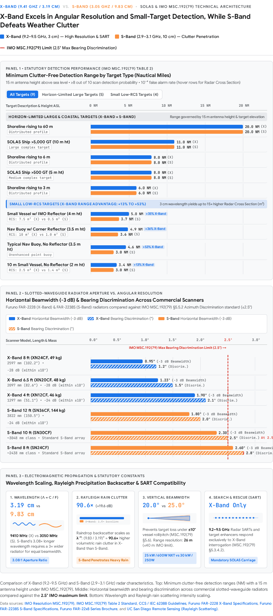
Antenna Aperture, Beamwidth, and Resolution Trade-Offs
Bearing (azimuth) resolution—the ability of a radar to display two targets at the same range as separate pips—is governed by the horizontal beamwidth ( , measured at the −3 dB half-power points) of the antenna1. By diffraction physics, horizontal beamwidth is directly proportional to wavelength (
 ) and inversely proportional to the horizontal aperture length (
 ) of the radiator (
 )1. Because S-band's wavelength (9.83 cm) is 3.08 times longer than X-band's (3.19 cm), an S-band slotted-waveguide array must be slightly over three times longer than an X-band array to achieve identical angular resolution1.
As demonstrated in commercial specifications for the Furuno FAR-2228 (X-band) and FAR-2238S (S-band) series, an 8 ft (2.60 m, 49.3 kg) X-band radiator (XN24CF) generates a razor-sharp 0.95° horizontal beamwidth and 1.2° bearing discrimination10. By contrast, an 8 ft S-band radiator (SN24CF) produces a 2.6° horizontal beamwidth and 2.8° bearing discrimination—which exceeds the IMO MSC.192(79) §5.5.2 statutory limit of 2.5° maximum bearing discrimination (requiring two point targets at the same range separated by 2.5° to be displayed as distinct objects on a ≤ 1.5 NM scale)3. Consequently, SOLAS-compliant S-band installations typically require a 10 ft (SN30CF, horizontal beamwidth 2.3°, bearing discrimination 2.5°) or 12 ft (SN36CF, 3.82 m, 144 kg, horizontal beamwidth 1.8°, bearing discrimination 2.0°) radiator14. Even with a 144 kg, 12 ft S-band scanner, angular resolution only matches that of a compact 4 ft (1.30 m, 46.2 kg) X-band scanner (XN12CF, horizontal beamwidth 1.9°, bearing discrimination 2.1°)10.
In the vertical plane, marine navigation radars do not resolve targets in elevation. Instead, they radiate a wide vertical fan beam—20° for X-band and 25° for S-band10. This wide vertical aperture ensures that surface targets remain continuously illuminated within the main vertical lobe without mechanical gimballing when own ship rolls or pitches up to the IMO MSC.192(79) §5.6 threshold of ±10° in heavy seas3. Unlike bearing resolution, radial range discrimination ( ) depends strictly on transmitted pulse duration (
 ) or pulse-compression bandwidth rather than carrier frequency1. Both X-band and S-band Furuno FAR-22x8 units achieve a minimum range of 22 m and range discrimination of 26 m on short pulses, surpassing the IMO MSC.192(79) requirement of 40 m minimum range and 40 m radial target separation3.
Range Performance and Weather Attenuation (Rain and Sea Clutter)
In clutter-free conditions with a standard 15 m antenna height, IMO MSC.192(79) Table 2 mandates identical detection ranges for both bands against large, horizon-limited targets: 20 NM for 60 m cliffs, 11 NM for SOLAS vessels > 5,000 GT (10 m height), and 8 NM for SOLAS vessels > 500 GT (5 m height)24. However, against small surface targets in calm seas, X-band achieves substantially longer detection ranges—such as 4.9 NM vs. 3.6 NM for a navigation buoy with a corner reflector and 4.6 NM vs. 3.0 NM for a typical unreflected navigation buoy—because small objects exhibit a much larger Radar Cross Section (RCS) at 3 cm (10 m² for a measurement corner reflector and 7.5 m² for an IMO reflector at X-band, versus 1.0 m² and 0.5 m² at S-band)3.
When weather deteriorates, the physical advantage reverses dramatically in favor of S-band3. Raindrops, snow, and hail have diameters smaller than both radar wavelengths, placing them primarily in the Rayleigh scattering regime (with transitions toward Mie scattering for large raindrops at X-band)32. Under Rayleigh theory, the volumetric backscattering intensity of precipitation varies inversely with the fourth power of wavelength ( )32. Comparing X-band (
 ) to S-band (
 )27:

Thus, a rain squall reflects 90.6 times (+19.6 dB) more clutter energy back into an X-band receiver than into an S-band receiver27, while simultaneously inflicting severe two-way path attenuation (ranging from 0.5 to 5.0 dB/km in heavy precipitation) that can mask targets behind or inside tropical downpours33. Similarly, radar backscatter from a rough sea surface arises from resonant Bragg scattering off short surface waves whose wavelength matches the incident radar wave (modulated by the slope of long ocean swell), alongside Rayleigh scattering from entrained air bubbles and sea spray thrown up by breaking wave crests32. Because X-band (~3 cm) couples directly with centimeter-scale capillary ripples and sea spray droplets, X-band displays experience heavier close-range sea clutter than S-band (~10 cm), allowing S-band to maintain superior target detection and tracking in heavy seas3.
Mandatory X-Band Requirement for 9 GHz Radar SART Detection
Under GMDSS and SOLAS Chapter V Regulation 19, conventional Search and Rescue Radar Transponders (SARTs) operate exclusively across the 9.2–9.5 GHz X-band (horizontally polarized, receiver sensitivity better than −50 dBm, effective radiated power ≥ 400 mW / +26 dBm)7. S-band (3 GHz) radars cannot trigger or detect a 9 GHz SART8.
When an X-band radar pulse interrogates a SART, the transponder wakes within < 0.5 µs and sweeps a voltage-controlled oscillator (VCO) across the full 9.2–9.5 GHz band 12 times within ≤ 100 µs, alternating between 0.4 µs fast sweeps and 7.5 µs slow sweeps13. Because the searching X-band radar receiver has a narrow intermediate-frequency (IF) passband centered on its transmitter frequency (e.g., 9410 MHz), it registers a brief pulse each time the SART's VCO sweeps across that passband13. At medium ranges (> 1 NM, typically 6–12 NM from a ship's bridge and > 30 NM from aircraft), only the 12 slow (7.5 µs) sweeps deliver enough energy to register, painting a line of 12 equally spaced dots along the SART's bearing separated by 0.6 to 0.64 NM (1,125 to 1,190 m)8. Because the initial sweep is fast (0.4 µs), the first dot appears within 150 m of the survival craft at close range (or up to 0.6 NM beyond at medium range if the initial fast sweep falls below threshold)13. Inside 1 NM, the 12 fast sweeps also break through the receiver threshold while side-lobe interrogation widens the dots into concentric arcs and finally 12 concentric circles, alerting rescuers that the survival craft is immediately alongside8.
To optimize a traditional X-band magnetron radar for SART search, the operator selects the 6 to 12 NM range scale, switches to Long pulse, disables A/C SEA (STC), A/C RAIN (FTC), Echo Averaging, and Interference Rejection (which can reject asynchronous SART sweeps), and if necessary manually detunes the receiver so normal clutter fades while the 300 MHz-wide SART sweep remains visible (returning to normal tuning immediately afterward)12. Modern solid-state X-band radars (such as the Furuno NXT series) incorporate dedicated SART processing that preserves SART detection across range scales43.
2. Transceiver & Antenna Architecture
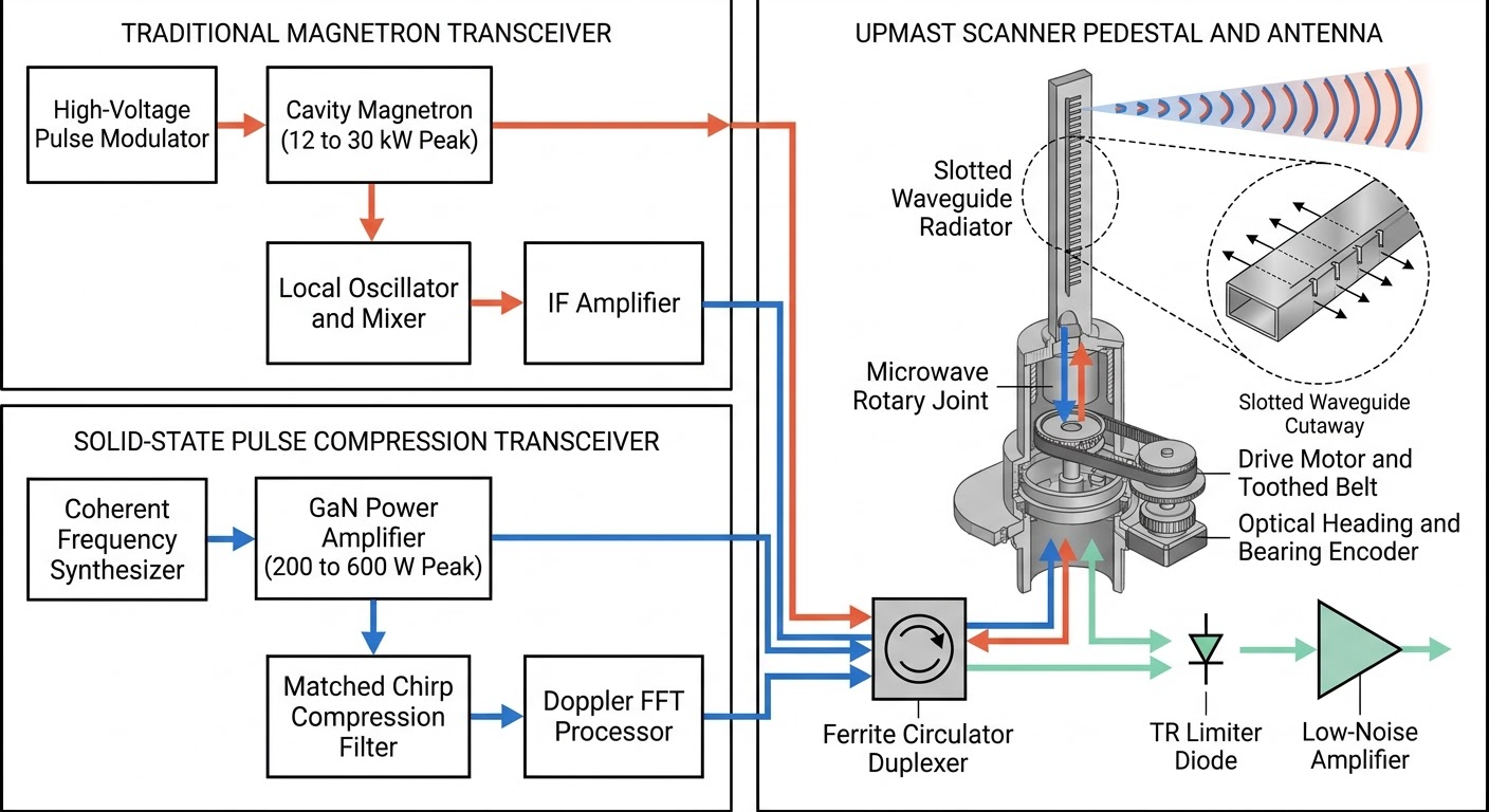
Traditional Cavity Magnetron Pulse Radars vs. Modern Solid-State Radars
Marine radar transmitters fall into two distinct RF engineering generations:
Architectural Parameter | Traditional Cavity Magnetron Radar | Modern Solid-State (Pulse Compression / Doppler) Radar |
|---|---|---|
RF Power Device | Vacuum cavity magnetron with heated barium-oxide cathode (MAF1565N, MG5436, MG5223F)44. | Gallium Nitride (GaN) Solid-State Power Amplifier (SSPA) module47. |
Nominal Peak Output Power | 12 kW or 25 kW (X-band, e.g., FAR-2218/2228); 30 kW (S-band, e.g., FAR-2238S)10. | 600 W (FAR-2228-NXT X-band), 250 W (FAR-2238S-NXT S-band), or < 200 W (SharpEye)49. |
Transmitted Waveform & Modulation | Single unmodulated rectangular carrier pulse (P0N): 0.07 to 1.2 µs duration10. | Dual P0N (0.06 to 1.2 µs for close range) + Q0N frequency-modulated chirp (4.68 to 20.59 µs, up to 10% duty cycle)11. |
Frequency Stability & Coherence | Non-coherent, free-running oscillation (±30 MHz tolerance); requires automatic/manual receiver LO tuning10. | Phase-coherent synthesizer (±5 MHz tolerance); enables Pulse Compression (up to 30 dB gain) and FFT Doppler processing11. |
Warm-Up Time & Consumables | ~3 minutes mandatory heater warm-up; magnetron degrades over 5,000–7,000 rated TX hours11. | Instant-on (warm-up excluded) from cold start; no consumable vacuum tube11. |
In a conventional magnetron radar, a high-voltage Pulse Modulator discharges short, multi-kilovolt DC pulses across a heated barium-oxide cathode inside a resonant cavity magnetron46. Electrons emitted by the cathode interact with the resonant anode cavities in a strong magnetic field, converting DC pulse energy into high-power microwave bursts (12 to 25 kW peak in X-band; 30 kW peak in S-band)46. Because the magnetron is a non-coherent oscillator whose frequency drifts with temperature and cathode aging, the superheterodyne receiver requires a voltage-tuned Local Oscillator (LO) feeding an Intermediate Frequency (IF) mixer to stay locked onto the carrier12. Furthermore, because pulse energy is the product of peak power and duration ( ), magnetron radars face a direct trade-off: short pulses (0.07 µs) provide fine range resolution (10.5 m spatial length) but low total energy, whereas long pulses (1.2 µs) provide high energy for long-range detection but coarse range resolution (179.9 m spatial length)27.
Modern solid-state transceivers (such as Furuno's NXT series and Kelvin Hughes's SharpEye) replace the magnetron with coherent Gallium Nitride (GaN) Solid-State Power Amplifiers (SSPAs) operating at peak powers of 200 to 600 W48. To achieve target detection equivalent to a 25 to 30 kW magnetron without sacrificing range resolution, solid-state radars utilize Pulse Compression29. On each transmission cycle, the Furuno FAR-2228-NXT transceiver emits a short unmodulated pulse (P0N, 0.06 to 1.2 µs at 83.75 MHz IF) to cover close ranges, paired with a long frequency-modulated chirp pulse (Q0N, spanning 4.68 µs on S1 up to 20.59 µs on L at 103.75 MHz IF, offset by 20 MHz in RF carrier frequency)11. In the receiver, the returning Q0N chirp passes through a matched compression filter that aligns the swept frequencies in time, compressing the long pulse into a narrow spike with up to 30 dB of pulse compression gain and a range resolution of 15 to 26 m10. Because the synthesized waveform is phase-coherent from pulse to pulse, solid-state systems also apply Fast Fourier Transform (FFT) Doppler filtering, using radial velocity phase shifts to separate moving targets from sea and rain clutter50.
Duplexers, Waveguides, and Upmast vs. Downmast Routing
Because a marine radar uses a single antenna for both high-power transmission and low-level reception (detecting signals down to −127 dBm with a < 5 dB receiver noise figure51), an RF Duplexer is required to isolate the sensitive receiver Low-Noise Amplifier (LNA / Microwave Integrated Circuit) during transmission5. Commercial marine radars employ a passive ferromagnetic Circulator paired with a T-R (Transmit-Receive) Limiter (either a TR cell or a solid-state PIN-diode limiter)46. Outgoing energy from the transmitter circulates to the antenna port, while incoming echoes from the antenna circulate to the receiver port. During the transmit pulse, any RF leakage across the circulator or reflected back from a mismatched waveguide triggers the TR limiter diode into conduction, clamping the spike before it can damage the front-end MIC LNA46.
Transceiver placement follows one of two physical topologies5. In a Downmast (TR-Down / RF-Down) installation, the transceiver is housed inside the bridge or mast cabin for accessible maintenance, and microwave energy is routed up the mast via a rectangular waveguide or coaxial feeder5. However, long waveguide runs introduce two-way attenuation losses, require precise flange torque, and suffer severe degradation if moisture condenses inside the guide45. In an Upmast (TR-Up / Transceiver Aloft) installation—standard on modern series such as the Furuno FAR-22x8 and Kelvin Hughes SharpEye—the transceiver is integrated directly inside the scanner pedestal beneath the antenna, eliminating the mast waveguide and its insertion losses while connecting to the bridge processor over Ethernet LAN or low-loss signal cables14.
Rotary Joint, Slotted-Waveguide Array, and Scanner Rotation
Inside the scanner pedestal, microwave energy transitions from the stationary duplexer into the rotating antenna boom through a concentric Microwave Rotary Joint that maintains RF continuity and low insertion loss across all 360° of rotation45. The radiator itself is a horizontally polarized Slotted-Waveguide Array enclosed within a fiberglass radome10. Narrow slots are milled into the wall of the horizontal waveguide; constructive interference across the radiating slots forms the narrow horizontal beam (0.95° to 2.6°) while keeping side-lobe radiation suppressed to −24 to −28 dB within ±10° of the main lobe and −30 to −32 dB outside ±10°10.
A geared electric motor and toothed drive belt rotate the scanner at 20 to 24 rpm (e.g., 24 rpm on Furuno FAR-22x8, 22 rpm on Kelvin Hughes and Gemrad; IEC 62388 standard minimum is 20 rpm) on conventional ships, and 40 to 45 rpm (42 rpm on Furuno HSC models; IEC 62388 HSC minimum is 40 rpm) on High-Speed Craft to provide rapid image renewal at high closing speeds5. An optical slotted disc and optocoupler mounted in the pedestal generate a Heading Pulse (HP) as the beam passes dead ahead and incremental Bearing Pulses (BP) to synchronize the bridge display azimuth46.
3. ARPA Target Tracking & Vector Modes
Target Acquisition, Tracking Gates, and Filtering Convergence
An ARPA or Target Tracking (TT) processor converts raw polar radar returns into kinematic tracks through a four-stage digital pipeline:
- Acquisition (Manual and Guard Zones): Watchkeepers acquire targets manually via trackball cursor or automatically by establishing two configurable Guard / Acquisition Zones (adjustable between 0.7 and 32 NM over any 1° to 360° sector)5. While IMO MSC.192(79) requires tracking at least 20 (Cat 3), 30 (Cat 2), or 40 (Cat 1) radar targets across the 3, 6, and 12 NM range scales, modern commercial processors (e.g., FAR-22x8) track up to 100 radar targets within 24–32 NM alongside 350 AIS targets3.
- Thresholding and Centroid Extraction: Once acquired, the processor places a 2D tracking gate in range and azimuth around the target's predicted position for the next antenna scan. Under IEC 62388 / MSC.192(79), the tracker maintains lock on targets detected in at least 5 out of 10 consecutive scans at relative speeds up to 100 knots (and up to 140 knots for HSC)5.
- Recursive Motion Smoothing: Because single-scan radar centroids fluctuate due to target glint, pitch, roll, and bearing quantization (within ±2° bearing and 50 m or ±1% range under MSC.192(79)12), ARPA smooths raw target positions through a recursive motion filter6.
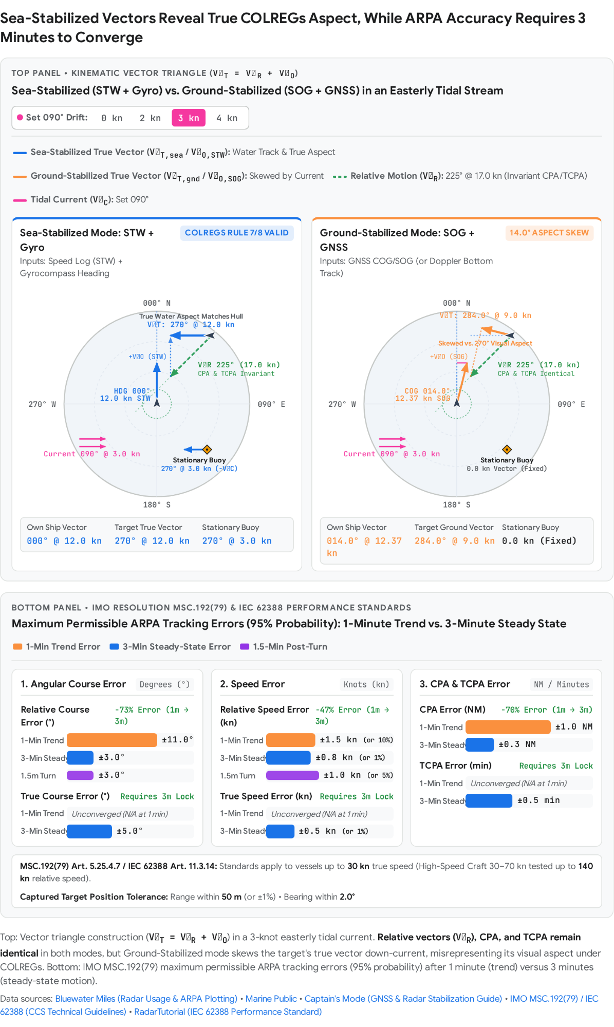
- Statutory Convergence Intervals (1-Minute Trend vs. 3-Minute Steady State): Because recursive smoothing requires multiple antenna scans to converge, 3 minutes of steady-state tracking must be allowed before relying on ARPA motion data for collision avoidance4. Under IMO Resolution MSC.192(79) §5.25.4.7 and IEC 62388 (at the 95% probability level for vessels up to 30 kn), tracking accuracy progresses from 1-minute trend accuracy (relative course within 11°, relative speed within 1.5 kn or 10%, CPA within 1.0 NM) to 3-minute steady-state accuracy (relative course within 3°, relative speed within 0.8 kn or 1%, CPA within 0.3 NM, TCPA within 0.5 min, true course within 5°, and true speed within 0.5 kn or 1%)12. Furthermore, 1.5 minutes after a turn is completed, tracking accuracy must recover to within ±3° in course and ±5% or ±1 kn in speed58.
Mathematical Calculation of CPA and TCPA
On each scan  , the radar measures a target's range
 and relative bearing
 (which is added to own ship's gyro heading
 to obtain true bearing
 )4. Converting polar coordinates into a local North-East Cartesian frame centered on own ship:

By tracking the rate of change of the target's relative position vector  over time, the ARPA filter estimates the target's Relative Velocity Vector
 . Assuming constant velocity vectors, the target's relative position at any future time
 is
 . Minimizing
 with respect to
 yields Time to Closest Point of Approach (TCPA) and Closest Point of Approach (CPA):


A positive TCPA indicates the target is closing; a negative TCPA indicates the target has already passed CPA and is opening. Crucially, because  and
 are derived directly from radar range and gyro-stabilized bearing measurements, Relative Vectors, CPA, and TCPA do not depend on own ship's speed input (STW or SOG)4.
To compute the target's True Velocity Vector ( , true course and speed), the ARPA performs vector addition of the measured relative velocity vector (
 ) and own ship's velocity vector (
 )4:
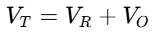
Consequently, any error or misrepresentation in own ship's heading or speed input ( ) directly corrupts the target's True Vector (
 ) while leaving the Relative Vector (
 ), CPA, and TCPA unchanged4.
Sea-Stabilized (STW) vs. Ground-Stabilized (SOG) Vectors
Because  , the operational meaning of the target's True Vector depends entirely on whether own ship's velocity
 is referenced to the water or to the seabed4:
Operational Dimension | Sea-Stabilized Mode (Water Reference) | Ground-Stabilized Mode (Bottom / GNSS Reference) |
|---|---|---|
Own-Ship Sensor Inputs ( | Speed Through Water (STW) from Doppler/EM Speed Log + True Heading (HDG) from Gyrocompass4. | Speed Over Ground (SOG) and Course Over Ground (COG) from GNSS (or bottom-track Doppler log)4. |
What Target True Vector ( | Target's Course and Speed Through the Water, directly reflecting the target's true heading / visual aspect4. | Target's Course and Speed Over the Ground (water motion vector plus tidal current vector |
Behavior of Stationary Targets (Buoys, Lighthouses) | Display a water vector equal in magnitude and opposite in direction to the tidal current ( | Remain stationary on True Motion display with zero vector4. |
COLREGs & Operational Role | Recommended for Collision Avoidance: Correctly displays target aspect (crossing, head-on, overtaking) under COLREGs Rules 7, 8, and 194. | Used for Coastal Navigation & Position Monitoring: Misrepresents target aspect in currents; not suitable for COLREGs assessment4. |
Vulnerability to GNSS Spoofing / Jamming | Resilient: Uses autonomous shipboard gyro and water speed log; remains reliable during GNSS spoofing9. | Highly Vulnerable: Spoofed GNSS SOG/COG corrupts ARPA true vectors and true motion trails9. |
 )
 ) Represents
 )4.
 )4.
To understand why Sea-Stabilized mode is required for collision avoidance, consider two vessels navigating in a strong tidal current ( )4. Both own ship and the target ship are floating inside the same moving body of water, so the current acts identically on both hulls (
 and
 ). Because relative velocity is the difference between the two vessels' velocities (
 ), the common current
 cancels out completely in relative motion. When the ARPA adds own ship's water velocity (
 , from Gyro HDG + Log STW) to
 , it recovers the target's velocity through the water (
 )—which corresponds to the direction the target's hull is heading (her aspect, determining whether she is crossing, head-on, or overtaking under COLREGs)4. Conversely, if the radar is placed in Ground-Stabilized mode, the ARPA adds own ship's ground velocity (
 ) to
 , yielding
 . In a strong cross-current, a crossing vessel's ground vector is skewed down-current from her actual heading—creating a dangerous discrepancy between radar-displayed aspect and visually observed aspect4. Furthermore, during GNSS spoofing incidents, satellite-derived SOG and COG diverge sharply from STW and Gyro Heading, corrupting Ground-Stabilized vectors; reconfiguring the radar to Sea-Stabilized mode (Gyro + Doppler log STW) isolates collision avoidance vectors from compromised satellite feeds9.
Target Swap and Tracking Limitations
Watchkeepers must actively guard against three inherent ARPA tracking limitations. First, Target Swap occurs when two tracked vessels pass closely, or when a tracked ship passes near a strong stationary echo (such as a buoy, pier, or clutter peak) so that both echoes occupy the same tracking gate simultaneously; the tracker may inadvertently transfer the target vector and historical state from one target to the other6. Second, Maneuver Smoothing Lag arises because the tracking filter averages returns over multiple scans: an abrupt course or speed alteration by a target vessel is not detected instantly, introducing a vector delay on the order of 15 to 30 seconds at high relative speed and 30 to 60 seconds at low relative speed6. Watchkeepers should use Echo Trails (Afterglow)—which display the raw historical track of echoes—to detect target maneuvers and target swaps immediately5. Third, on ultra-short range scales (0.25 NM) or at high closing speeds, a target echo can jump across the display between scans (for example, at 42 rpm, a fast target can jump 59 m per scan, corresponding to 23 mm on a 360 mm display at the 0.25 NM scale), causing the ARPA to lose track amidst close-in sea clutter5.
4. Signal Processing & Clutter Suppression
Receiver Gain Control
The Gain control adjusts the overall amplification of the receiver's Intermediate Frequency (IF) and video amplifier stages, setting the sensitivity threshold required to display an echo12. Because receiver sensitivity is bounded at the lower end by internal thermal noise (typically a < 5 dB noise figure with a minimum detectable signal below −127 dBm51), Gain must be set so that a light, uniform thermal noise speckle is barely visible across the display. Setting Gain too low clips weak echoes from small craft or buoys off the screen, whereas setting Gain too high saturates the display with background noise and clutter, amplifies side-lobe and multiple-bounce false echoes, and degrades ARPA tracking6.
Sea Clutter Suppression: STC (Sensitivity Time Control / A/C SEA)
Sea waves surrounding own ship produce strong backscatter whose return power decreases rapidly with radial distance, creating a dense clutter zone around the display origin54. Sensitivity Time Control (STC) suppresses this close-range saturation via a programmed variable attenuator positioned in the receiver channel behind the receiver protector/limiter (providing a dynamic range of up to 140 dB with STC active)51. Triggered at the end of each transmitted pulse, STC applies maximum attenuation at minimum range and reduces that attenuation progressively with elapsed sweep time until attenuation reaches 0 dB at the edge of the sea clutter zone, beyond which full receiver amplification is restored54. Because STC attenuates all returns within its swept-time window indiscriminately, setting STC (A/C SEA) too high to completely clear the screen of sea clutter will also erase small close-in targets (such as navigation buoys or small boats)6.
Rain Clutter Suppression: FTC (Fast Time Constant / A/C RAIN) and CFAR
Precipitation cells (rain, snow, hail) occur at any range and produce spatially extended returns that saturate the display into solid blobs, masking vessels inside or behind the storm54. Fast Time Constant (FTC) acts as a high-pass differentiator (implemented in analog receivers as a short-time-constant circuit and in digital processors via adjacent range-register subtraction)54. When a radar pulse enters a uniform rain squall, the video amplitude rises at the storm's boundary and remains constant across the cell's interior. The FTC circuit passes only the rapid leading-edge transitions—displaying the front edge of the rain boundary while differentiating the flat interior of the rain cloud back down toward the baseline54. If a solid vessel is inside the rain cell, its steeper leading-edge echo rises above the surrounding rain backscatter and passes through the differentiator, unmasking the target54. Because excessive FTC reduces overall signal energy and can suppress weak targets or SART sweeps6, modern radars complement or replace manual FTC with Constant False Alarm Rate (CFAR) processing and automated filters (such as Furuno's ACE – Automatic Clutter Elimination), which dynamically adapt detection thresholds to local clutter levels49.
Pulse Length Selection (Short, Medium, Long) and Clutter Cell Volume
Commercial radars provide up to six selectable pulse lengths (S1, S2, M1, M2, M3, L) coupled to specific Pulse Repetition Frequencies (PRFs), maximum unambiguous ranges ( ), and matched receiver IF bandwidths10:
Pulse Designation | Nominal P0N Duration (τ) | Solid-State Q0N Chirp Duration | Radial Spatial Length (ΔR = cτ / 2) | Typical PRF (Magnetron / Solid-State) | Unambiguous Range (Runamb, Mag / SS) | Matched Receiver IF Bandwidth (P0N) | Primary Operational Application |
|---|---|---|---|---|---|---|---|
S1 (Short 1) | 0.06–0.08 µs1 | 4.68 µs26 | 9.0–12.0 m27 | 3000 Hz / 1500 Hz10 | 27.0 NM / 54.0 NM27 | 44.9–46.8 MHz26 | Harbour pilotage, docking, high-resolution anti-clutter (0.125–1.5 NM)47. |
S2 (Short 2) | 0.15 µs26 | 7.02 µs26 | 22.5 m27 | 3000 Hz / 1500 Hz10 | 27.0 NM / 54.0 NM27 | 33.0–36.7 MHz26 | Confined coastal waters, heavy rain/sea clutter (0.5–3 NM)47. |
M1 (Medium 1) | 0.30 µs26 | 8.89 µs26 | 45.0 m27 | 1500 Hz / 1200 Hz10 | 54.0 NM / 67.5 NM27 | 25.7–26.6 MHz26 | Coastal navigation and traffic separation schemes (1.5–6 NM)47. |
M2 (Medium 2) | 0.50 µs26 | 13.57 µs26 | 75.0 m27 | 1200 Hz / 1000 Hz10 | 67.5 NM / 80.9 NM27 | 18.3–19.3 MHz26 | Standard collision avoidance watchkeeping (3–12 NM)47. |
M3 (Medium 3) | 0.70 µs26 | 13.57 µs26 | 104.9 m27 | 1000 Hz / 1000 Hz10 | 80.9 NM / 80.9 NM27 | 12.8 MHz26 | Medium-to-long-range target tracking (6–24 NM)47. |
L (Long) | 1.20 µs26 | 20.59 µs26 | 179.9 m27 | 600 Hz (500 Hz at 96 NM)10 | 134.9 NM (161.9 NM)27 | 9.2 MHz (6.4 MHz Q0N)26 | Open-ocean landfall, SART detection, Performance Monitor (12–96 NM)42. |
Selecting the proper pulse length directly governs both radial range discrimination and clutter cell volume1. Because two targets on the same bearing can only be resolved if the time interval between their echoes exceeds the transmitted pulse duration, radial range resolution is bounded by  1. A Short Pulse (S1: 0.06–0.08 µs) occupies only 9.0 to 12.0 m radially in space, delivering a practical range discrimination of 25 to 26 m—well inside the 40 m IMO MSC.192(79) range discrimination limit1. Equally important, the instantaneous volume of rain or sea surface illuminated by the radar pulse is proportional to pulse length (
 ). Switching from Long Pulse (1.20 µs, 179.9 m radial footprint) to Short Pulse S1 (0.07 µs, 10.5 m radial footprint) reduces the radial clutter cell extent by a factor of 17.1, making Short Pulse selection essential for target discrimination in heavy rain or sea clutter1. Conversely, Long Pulse (1.20 µs) concentrates 17 times more pulse energy on distant targets while switching in a narrow receiver IF passband (9.2 MHz vs. 44.9–46.8 MHz on S1), lowering the receiver noise floor for maximum clear-weather detection range, SART interrogation, and Performance Monitor testing16.
5. Limitations, False Echoes & Maintenance
Blind Sectors, Shadow Sectors, and Spurious False Echoes
Because microwave propagation is quasi-optical, shipboard obstructions, antenna radiation patterns, and atmospheric anomalies generate distinct false echo signatures that watchkeepers and marine engineers must diagnose2:
Phenomenon / False Echo | Physical Generation Mechanism | Characteristic PPI Signature | Operational Mitigation & Diagnostic Action |
|---|---|---|---|
Blind Sector | Complete physical blockage of the radar beam by close shipboard structures (funnels, masts, cranes, Samson posts)60. | Total absence of target echoes, sea clutter, or land returns within a fixed relative bearing arc60. | Measure during sea trials and post Blind/Shadow Sector Diagram at display; cross-check with second radar mounted on an offset mast60. |
Shadow Sector | Partial blockage and edge diffraction of the beam around a shipboard obstacle or island, creating an attenuated zone behind it60. | Weakened sea clutter and faint, intermittent target echoes across a wider, less distinct relative bearing sector60. | Maintain visual lookout and compare with secondary radar or visual bearings to unmask small targets hidden in the shadow sector60. |
Indirect (Ghost) Echoes | Transmitted pulse reflects off an onboard obstruction (funnel, crane, crosstree) toward a real target and returns along the same path2. | False echo appears along the relative bearing of a shadow/blind sector, but at the exact same range as the real target2. | Recognize that echoes inside a known shadow sector bearing matching a strong real target's range are reflections; can be blanked via sector blanking2. |
Side-Lobe Echoes | Residual side lobes (−24 to −32 dB off the main beam) reflect off a strong close target (< 1–2 NM) before and after the main lobe passes14. | Symmetrical broken arcs or dotted smears flanking a bright real target at the exact same range on either side in azimuth60. | Reduce Gain or apply light STC (A/C SEA) until the flanking side-lobe arcs vanish leaving the central main-lobe pip60. |
Multiple-Bounce Reflections | Pulse bounces repeatedly back and forth between own ship's hull and a close (< 1 NM), highly reflective ship or breakwater on a parallel course1. | A radial line of 2, 3, or more pips along the exact same bearing at double ( | Only the innermost echo ( |
Second-Trace Echoes | Under super-refraction or atmospheric ducting, a pulse travels far beyond the unambiguous range ( | Distant land or ships (> 27–54 NM) appear falsely at close range ( | Enable Second-Trace Echo Rejector (which lowers PRF, e.g., from 1500 Hz to 1000/600 Hz), causing second-trace echoes to shift range or vanish26. |
 ), triple (
 ), and quadruple (
 ) the true range2.
 ) is real; reduce Gain/STC and avoid acquiring outer multiple-bounce pips into ARPA60.
 ) and returns after the next pulse is transmitted2.
 ) on their true bearing2.
Anomalous Propagation and Second-Trace Mechanics
Normally, atmospheric refraction bends the radar beam slightly downward, extending the radar horizon modestly beyond the geometric horizon to  (where
 is height in meters)2. Under sub-refraction (when air temperature falls faster than the standard lapse rate of 0.65°C/100 m or relative humidity increases with height, typically over cold high-latitude waters or warm currents), the beam bends upward away from the surface, reducing detection range by up to 20%2. Conversely, under super-refraction and surface ducting (when temperature falls slower than 0.65°C/100 m or a temperature inversion coincides with a sharp drop in relative humidity with height), the radar wave bends downward sharply and reflects repeatedly off the sea surface inside an atmospheric duct, extending radar range by 40% or more2.
When super-refraction or ducting occurs while operating at a high PRF, second-trace echoes appear2. For example, at a PRF of 1500 Hz (Pulse Repetition Interval  ), the maximum unambiguous range is27:

If a ducted pulse reflects off a distant target at  , the echo arrives 66.7 µs after the next pulse leaves the scanner, registering as a false short-range target on the second trace at
 2. If consistent enough, ARPA can acquire and track a second-trace echo, generating erroneous course and speed vectors73. Activating the Second-Trace Echo Rejector modifies the PRF (for instance, on the Furuno FAR-2228-NXT, switching to 2nd Trace Mode reduces S1/S2 PRF from 1500 Hz to 1000 Hz and M1–M3 PRF from 1200/1000 Hz to 600 Hz26), expanding
 to 80.9–134.9 NM and shifting or eliminating the false echo26.
Routine Maintenance, Component Lifespans, and the Performance Monitor
Maintaining statutory compliance and detection performance aboard commercial vessels requires scheduled preventative maintenance and regular performance monitoring4:
Subsystem / Component | Representative Part Numbers (Furuno FAR-21x7 / FAR-22x8) | Rated Service Life / Interval | Failure Symptoms & Preventative Maintenance Protocol |
|---|---|---|---|
X-Band Magnetron (12 kW / 25 kW) | MAF1425B, MAF1565N (NJT1565), MG5436, MG5241F, FNE120144 | 5,000 TX hours manufacturer table (service guides report 2,500–4,000 h up to 8,000–10,000 h depending on duty)44 | Peak power drops < 80%, weak echoes > 10 NM, off-center tuning, HV overcurrent arcing, PM arc loss45. Season replacement tube in STBY for 20–30 min before TX to evacuate trace gas46. Reset TX hour meter after replacement44. |
S-Band Magnetron (30 kW) | MG5223F44 | 7,000 TX hours manufacturer table (up to 10,000–15,000 h field estimates)44 | Gradual loss of output power and distant echoes; eliminated completely on solid-state NXT / SharpEye models49. |
Scanner Drive Motor & Carbon Brushes | Motors: D8G-516, RM-7398, BV2-K155/K156; Brushes: MG120-5X6X1144 | 10,000 hours44 | Antenna stall alarm or irregular RPM46. Inspect/replace carbon brushes during magnetron changes; verify drive belt tension and replenish gearbox oil44. |
Heading / Bearing Optical Encoder | Slotted optical disc & optocoupler PCB inside pedestal46 | Inspect at overhaul / fault alarm46 | Heading Pulse (HP) or Bearing Pulse (BP) error alarm; unstable North-Up stabilization46. Clean optical disc and verify HP/BP waveforms with oscilloscope at SPU test pins46. |
Waveguide, Rotary Joint & Pedestal Seals | Microwave rotary joint, TR limiter diode, neoprene door gaskets, desiccator46 | Inspect annually / dry-dock46 | Moisture ingress causes high clutter, poor tuning, and waveguide loss; blown MIC limiter diode causes loss of echoes46. Renew gaskets and silica gel desiccant packs46. |
Display & Processor Consumables | LCD assembly (MU-190/231), CPU fan, HDD, CMOS battery (CR2032/CR2450)44 | Battery: 3–10 yr; Fan/HDD: 17,500–20,000 h; LCD: 50,000 h44 | Replace lithium backup batteries on schedule to prevent loss of system settings6. |
Required by IMO Resolution MSC.192(79) and SOLAS Chapter V on all vessels ≥ 300 GT, the built-in Performance Monitor (PM) must be checked before departure and every 4 hours while the radar is in operation to verify whether overall transmitter/receiver performance has degraded relative to commissioning baseline4. Incorporated inside the antenna unit, the Performance Monitor injects and receives a calibrated microwave test signal across the scanner aperture42. When activated on a Furuno FAR-21x7/22x8 radar, the system automatically configures to a standardized test state: 24 NM range scale, Long pulse, Auto tuning, and switches A/C SEA, A/C RAIN, Echo Stretch, Echo Averaging, and Interference Rejection OFF16. Under normal operating conditions, the radar displays one or two concentric arcs, with the innermost arc appearing between 13.5 NM and 18.5 NM within a 90° sector behind own ship42. The Performance Monitor is calibrated to observe a total of 10 dB loss across the transmitter and receiver: if no arc is displayed (or if transmit power drops by > 3 dB during service testing), the magnetron or front-end receiver chain has suffered excessive degradation and requires immediate bench diagnostics and overhaul42.
References
- 04 THE MARINE RADAR - pfri.uniri.hr, https://www.pfri.uniri.hr/bopri/documents/30_Marineradar_000.pdf
- Understanding Marine Radar Functionality | PDF - Scribd, https://www.scribd.com/presentation/406709285/4-Radar
- RESOLUTION MSC.192(79) (adopted on 6 December 2004, https://wwwcdn.imo.org/localresources/en/KnowledgeCentre/IndexofIMOResolutions/MSCResolutions/MSC.192(79).pdf
- Radar Usage and Plotting - Bluewater Miles, https://bluewatermiles.com/docs/radar-usage-and-plotting.pdf
- FAR-FR2805 Operator's Manual: Marine Radar ARPA Series, https://www.studocu.vn/vn/document/truong-dai-hoc-giao-thong-van-tai-tp-hcm/khoa-hoc-hang-hai/far-fr2805-operators-manual-marine-radar-arpa-series-overview/127815182
- marine radar - OPERATOR'S MANUAL, https://brimrun.is/wp-content/uploads/2023/02/OME36521E1_FAR2xx8.pdf
- Solas Chapter V - Annex 16 - Radar Equipment | PDF - Scribd, https://www.scribd.com/document/464639731/Solas-Chapter-V-Annex-16-Radar-Equipment
- Search and rescue transponder - Wikipedia, https://en.wikipedia.org/wiki/Search_and_rescue_transponder
- OOW Guide to GNSS Spoofing: Detecting and Navigating False, https://captainsmode.com/gnss-spoofing-oow-guide/
- FURUNO SPECIFICATIONS OF MARINE RADAR FAR-2228, https://www.furuno.it/docs/SPECIFICATIONSSP_FAR2228_MARINE_RADAR.pdf
- Model: FAR-2xx8 series - Furuno, https://www.furuno.com/files/Brochure/FAR-2xx8series_EN.pdf
- n-01 marine radar, https://www.ccs.org.cn/ccswzen/file/download?fileid=201950000000002643
- 86-920-005N Iss 3 ECI SART II User Manual - Norman Marine, https://norman-marine.ru/documents/SAILOR%20SART%20II%20User%20manual.pdf
- Furuno FAR-2228 Radar Installation Guide | PDF - Scribd, https://www.scribd.com/document/696516272/FAR-22x8series-EN
- NAutical Supplies JRC CATALOGUE 2020, https://www.nauticalsupplies.com.au/downloads/NS_Catalogues/Nautical-Supplies-JRC-Catalogue-2020-PRINT.pdf
- Installation Manual MARINE RADAR Model FAR-2218(-BB)/2228, https://furuno.it/docs/INSTALLATION%20MANUALIME36520B_FAR2xx8.pdf
- R5000 Processor - Installation manual, https://marine-electronics-manuals.com/maxabcpdf/rad_sim/rad_sim23.pdf
- Marine Radar Installation Manual | PDF - Scribd, https://www.scribd.com/document/624731408/far1513
- MARINE RADAR/ARPA FAR-2117/2127/2817/2827 FAR-2117-BB, http://www.morse.gr/Manuals/FAR2XX7%20Installation.pdf
- jrc-handbook-2015.pdf, https://www.fcmarine.co.uk/wp-content/uploads/2017/11/jrc-handbook-2015.pdf
- SOLAS V Reg 19 | PDF | Navigation | Tonnage - Scribd, https://www.scribd.com/document/361683106/SOLAS-V-Reg-19
- OPERATOR'S MANUAL - Furuno France, https://www.furuno.fr/docs/OPERATOR%20MANUALFAR21x7_21x7BB_28x7_OME-P31.pdf
- QinetiQ, http://www.kjeng.kr/upload/tech/20230104175335/JMA-9172-SA_MED-B_100813-130917_QQ.pdf
- MSC.192(79) Adoption of the Revised Performance Standards For, https://rise.odessa.ua/texts/MSC192_79e.php3
- 50 Navigation Q&A for Second Officer Exam & Interview Prep, https://www.marinepublic.com/blogs/training/640705-50-navigation-q-a-for-second-officer-exam-interview-prep
- https://fccid.io/ADB9ZWRTR123/Test-Report/Test-Report-4639123.pdf
- unknown_url
- https://www.furuno.it/docs/SPECIFICATIONSSP_FAR2238S_MARINE_RADAR.pdf
- Model: FAR-22x8 series Keep Steady at Sea - Nautical, https://www.nautical.es/wp-content/uploads/2018/12/05-FAR-22x8-folleto-eng.pdf
- Furuno USA - OPERATOR'S MANUAL, https://www.furunousa.com/-/media/sites/furuno/document_library/documents/manuals/public_manuals/far2xx8_operators_manual_for_far2258_far2268ds.pdf
- 5.3 Detection Performance and Anti-clutter Functions - imorules, https://www.imorules.com/GUID-2141E6DF-030D-414F-B752-6466EA3A3B9C.html
- Lecture 7: Propagation, Dispersion and Scattering, https://topex.ucsd.edu/rs/Lec07.pdf
- Evaluation of X-Band Dual-Polarization Radar-Rainfall Estimates, https://journals.ametsoc.org/view/journals/hydr/20/9/jhm-d-19-0097_1.pdf
- Principles of Modern Radar, https://ftp.idu.ac.id/wp-content/uploads/ebook/tdg/ADNVANCED%20MILITARY%20PLATFORM%20DESIGN/Principle%20Modern%20Radar.pdf
- Remote Sensing Study Guide (2027) | Scio.ly, https://www.scio.ly/guides/remote-sensing
- measurement of attenuation with airborne and ground-based radar, https://ntrs.nasa.gov/api/citations/20020013938/downloads/20020013938.pdf
- On the detectability of ocean surface waves by real and ... - MPG.PuRe, https://pure.mpg.de/rest/items/item_2514761_2/component/file_3514868/content
- SAILOR SART II 9GHz Search And Rescue Transponder, https://www.telemarno.no/files/Products/Beacon/SART/sailor_sart_ii_-_039315a.pdf
- SART (Search and Rescue Radar Transponder), https://www.nsrmarine.com/ueditor/php/upload/file/20220617/1655457406664841.pdf
- SAR-9, https://scortel.com/en/products/marine-communication-and-navigation/gmdss/item/download/209_df0e83fefeca42eaca1d3207b0b7ab26
- Search and Rescue Transponder (SART) for Safety at Sea, https://www.nautilusshipping.com/news-and-insights/what-is-a-search-and-rescue-transponder-sart
- OPERATOR'S MANUAL - Rcom Marine Equipment, https://www.rcom.nl/wp-content/uploads/2014/09/Furuno_FAR2127_Operators_Manual.pdf
- marine radar - OPERATOR'S MANUAL, https://www.furuno.it/docs/OPERATOR_MANUAL/FAR2xx8_OME-L.pdf
- Life Expectancy of Major Parts of FURUNO FAR2XX7 Radar - News, https://www.malinsmarine.com/news/life-expectancy-of-major-parts-of-furuno-far2xx7-radar.html
- Furuno FAR-2127 Magnetron Replacement Guide - Aurora Marine, https://auroramarinesupply.com/blog/furuno-far-2127-magnetron-replacement
- Furuno FAR-2127 X-Band RADAR: Magnetron Replacement, https://seanav.org/furuno-far-2127-x-band-radar-magnetron-repair-service/
- RADAR - Model: FAR-22x8 series - Furuno Italia, https://www.furuno.it/docs/DOCUMENTATION_COMMERCIALE/FAR-22x8series_en_A4.pdf
- Furuno FAR-2228-NXT X-Band RADAR - Seanav Marine, https://seanav.org/furuno-far-2228-nxt-x-band-radar-magnetron-repair-service/
- MARINE RADAR FAR-2xx8 series | FURUNO Product Solutions, https://www.furuno.com/en/products/radar/far-2xx8/index.html
- Kelvin Hughes Produce New Network Radars - ElectroMed, https://www.electromedmarine.com/kelvin-hughes-produce-new-network-radars/
- Olympus-200 Surveillance Radar Specs | PDF - Scribd, https://www.scribd.com/document/927368581/AT23010E-Technical-Annex-for-Olympus-200-20-D
- FAR21x7 28x7 Operator's Manual P 4-8-11 | PDF | Battery (Electricity), https://www.scribd.com/document/325501156/FAR21x7-28x7-Operator-s-Manual-P-4-8-11
- Life Expectancy of Major Parts of FURUNO FAR2XX8 Radar - News, https://www.malinsmarine.com/news/life-expectancy-of-major-parts-of-furuno-far2xx8-radar.html
- REAL TIME IMPLEMANTION OF STC AND FTC RADAR ... - IJRET, https://ijret.org/volumes/2013v02/i09/IJRET20130209014.pdf
- اجلزء الثاين - الاتحاد العربي للكهرباء, https://auptde.org/sites/default/files/2019-12/%D9%82%D8%A7%D9%85%D9%88%D8%B3%20%D8%A7%D9%84%D9%85%D8%B5%D8%B7%D9%84%D8%AD%D8%A7%D8%AA%20%D8%A7%D9%84%D9%85%D8%AA%D8%B9%D9%84%D9%82%D8%A9%20%D8%A8%D9%82%D8%B7%D8%A7%D8%B9%20%D8%A7%D9%84%D8%B7%D8%A7%D9%82%D8%A9%20%D8%A7%D9%84%D9%83%D9%87%D8%B1%D8%A8%D8%A7%D8%A6%D9%8A%D8%A9%20-%20%D8%A7%D9%84%D8%AC%D8%B2%D8%A1%20%D8%A7%D9%84%D8%AB%D8%A7%D9%86%D9%8A.pdf
- 电子对抗英汉、汉英、缩略语词典第6章_英汉部分 - 云起书院, https://m.yunqi.qq.com/read/654999/6
- 英汉部分_电子对抗英汉、汉英、缩略语词典最新章节在线阅读, https://m.chuangshi.qq.com/read/654999/6
- IEC 62388 - Radartutorial, https://www.radartutorial.eu/19.kartei/07.naval/pubs/100273_1.pdf
- Marine Electronics Products - GEM ELETTRONICA, https://www.gemrad.com/wp-content/uploads/2026/01/Marine_Electronics_Products.pdf
- Blind vs Shadow Sector in Radar | PDF - Scribd, https://www.scribd.com/document/945891246/Radar-Written-Class-Notes
- Every Radar Term You've Heard But Never Fully Understood, https://www.marinepublic.com/blogs/training/523766-every-radar-term-you-ve-heard-but-never-fully-understood
- Speed Through Water (STW) vs. Speed Over Ground (SOG), https://www.youtube.com/watch?v=fm6OjqLvlDM
- How are you using AIS? - Page 3 - Professional Mariner Forum, https://forum.gcaptain.com/t/how-are-you-using-ais/45959?page=3
- 7.1 Model Course 1.07 Radar Navigation at Operational Level, 2017, https://www.scribd.com/document/776909155/7-1-Model-Course-1-07-Radar-Navigation-at-Operational-Level-2017-Edition
- Bridge Team Radar Q&A: 72 Essential Questions for Mariners, https://www.marinepublic.com/blogs/training/811817-bridge-team-radar-q-a-72-essential-questions-for-mariners
- ARGUS RADAR SYSTEM - Norman Marine, https://norman-marine.ru/documents/ArgusRadar-System_User%20Manual.pdf
- Modern Radar Systems, https://ftp.idu.ac.id/wp-content/uploads/ebook/tdg/ADNVANCED%20MILITARY%20PLATFORM%20DESIGN/Modern%20Radar%20Systems,%202nd%20Edition.pdf
- Clutter suppression in radars by an application of digital filters to MTI, https://upload.wikimedia.org/wikipedia/commons/a/a7/Clutter_suppression_in_radars_by_an_application_of_digital_filters_to_MTI_systems._%28IA_cluttersuppressi00sarr%29.pdf
- MDC-7000/7900 Series Installation Manual - Nautic Center, https://www.nautic-center.se/Files/Images/Ecom/Product%20files/KO-MDC-7025-4_INSTALLATION.pdf
- MDC-2900 Series - SI-TEX, https://www.si-tex.com/upload/koden-manuals/1722952702162583980216256703951405299943mdc-2900_ime_rev07.pdf
- Furuno FAR-2117/2127/2137S Radar Manual | PDF - Scribd, https://www.scribd.com/document/554027380/FAR-2117
- Radar And Arpa Manual [2 ed.] 0750664347, 9780750664349, https://dokumen.pub/radar-and-arpa-manual-2nbsped-0750664347-9780750664349-9781423722762.html
- OPERATOR'S MANUAL, https://www.furuno.it/docs/OPERATOR%20MANUALOME36520B_FAR2xx8.pdf
- MARINE RADAR/ARPA - Instructions Manuals, https://www.instructionsmanuals.com/sites/default/files/2019-06/Furuno-FAR2117-en.pdf
- Furuno Radar Magnetron Lifespan Inquiry | PDF - Scribd, https://www.scribd.com/document/723905674/Furuno-Radar-Magnetron-Replacement