Part 1: System cardDel 1: Systemkort
1. Core Function
Shipboard maneuvering coordinates steering gear, rudders, and tunnel thrusters to control heading and lateral motion across all speeds1. At transit speeds, bridge helm or autopilot commands actuate electro-hydraulic steering gear to turn the rudder inside the accelerated propeller slipstream, creating hydrodynamic lift that alters course2. During low-speed docking, tunnel thrusters pump water transversely through hull ducts for bow and stern lateral thrust1, complemented by high-lift rudders deflecting 45°–70° to vector propeller wash sideways8.
2. Primary Operational Tasks
- Hydrodynamic Course Changing: Maintain heading via closed-loop PID autopilot or manual Follow-Up (FU) steering, converting rudder deflection in the propeller race into turning lift3.
- Rapid Rudder Swing: Slew the rudder across full travel (35° port to 35° starboard) and complete 35° to 30° opposite travel within 28 s at deepest seagoing draught and maximum ahead service speed10.
- Low-Speed Transverse Thrust: Generate lateral bow and stern sway forces and yaw moments via tunnel thrusters during harbour berthing, low-speed maneuvering, and dynamic positioning1.
- High-Angle Thrust Vectoring: Deflect high-lift flap or fishtail rudders to 45°–70° during low-speed harbour operations to direct propeller outflow sideways for stern crabbing8.
- Emergency Steering & Redundancy: Preserve directional control via bridge Non-Follow-Up (NFU) levers, direct local steering-flat actuation, automatic hydraulic isolation, and emergency power changeover within 45 s2.
3. System Interconnections
- Inputs: Control commands from the autopilot (comparing set course against gyrocompass heading), Follow-Up bridge wheels/tillers, spring-loaded Non-Follow-Up levers, local steering-compartment push-buttons/solenoids, and thruster remote consoles2; power supplies from Main and Emergency Switchboards (or an independent steering-flat power source), plus VFD/starter, hydraulic, or diesel thruster drives10; feedback and condition signals from rudder hunting gear, rudder stock angle transmitters, hydraulic reservoir low/low-low float switches, oil temperature/pressure gauges, and motor overload/phase monitors2.
- Outputs: Physical rudder stock torque (kNm) driving rudder rotation and transverse tunnel water-jet thrust producing hull sway forces and yaw moments7; synchronized Rudder Angle Indicator (RAI) displays on the bridge and in the steering gear compartment2; audible and visual alarms to both the bridge and Engine Control Room (ECR) for hydraulic low oil level, high oil temperature, power failure, motor overload, three-phase failure, control circuit failure, and autopilot heading deviation4.
4. Redundancy & Criticality
Under SOLAS Chapter II-1 Regulation 29, the main steering gear must move the rudder from 35° on one side to 35° on the other, and from 35° either side to 30° on the other in ≤28 s at deepest draught and maximum ahead service speed; where fitted, auxiliary gear must sweep 15° to 15° in ≤60 s at half maximum ahead service speed or 7 knots, whichever is greater10. Tankers, chemical tankers, and gas carriers of ≥10,000 GT and all other ships of ≥70,000 GT require two or more identical power units10. On tankers ≥10,000 GT, a single piping or power-unit failure (excluding tiller, quadrant, or actuator seizure) must trigger automatic fluid-loss detection and hydraulic isolation (in interconnected arrangements) or switchover between independent systems so steering capability is regained within ≤45 s10. For vessels with rudder stock diameters of 230 mm and above20, automatic emergency power must supply a compliant power unit, its controls, and the RAI within ≤45 s for at least 30 minutes (≥10,000 GT) or 10 minutes (smaller ships)10.
Part 2: Technical deep diveDel 2: Teknisk dybdeanalyse
1. Electro-Hydraulic Steering Gear Types
Electro-hydraulic steering gears convert pressurized hydraulic oil flow into high-torque rotational motion at the rudder stock through two dominant actuator configurations: ram-type linear hydraulic cylinders paired with a Rapson slide mechanism, and rotary vane actuators mounted directly onto the rudder stock2.
Ram-type steering gears use 2-ram or 4-ram hydraulic cylinders arranged in parallel pairs driving a fork tiller or round-arm crosshead keyed to the rudder stock23. In the Rapson slide geometry, sliding crosshead blocks allow the fixed-axis linear rams to push perpendicularly against a rotating tiller arm22. As the rudder rotates to angle  away from amidships (0°), the effective moment arm lengthens geometrically, amplifying delivered torque by
 22:

Here,  is rudder stock torque,
 is total linear force across
 active rams of piston area
 under working pressure
 , and
 is the perpendicular crosshead radius at midships22. Evaluating
 directly yields a mechanical advantage of 1.00× at 0°, 1.13× at 20°, 1.49× (+49%) at 35°22, and 2.00× at 45° (134.2% of the 35° rating). Because hydrodynamic rudder torque increases steeply toward hard-over, the Rapson slide matches rising load demand with rising mechanical advantage29. By contrast, ram geometries connected through articulated links or oscillating cylinders lose mechanical advantage toward hard-over29. Manufacturer datasheets reflect this torque amplification: Hatlapa's Poseidon ram-type series rates working torque at 35°, noting approximately 82% of rated torque at 20° and 134% at 45°30. Ram systems operate cleanly at high hydraulic pressures—such as 100 bar working / 125 bar design pressure in Hatlapa Neptune specifications30, or an illustrative 110 bar sizing example in engineering guides where four 280 mm bore rams generate ~391 kNm at 35°22—enabling compact cylinders and extreme capacities up to 8,893 kNm in 4-cylinder Poseidon ST models23.
Rotary vane steering gears eliminate external rams, crossheads, and tillers15. A cylindrical stator housing with fixed internal stoppers bolts to the hull structure, while an internal rotor carrying radial vanes locks onto the tapered rudder stock via a hydraulic pull-up nut15. Pressurizing opposing chambers between the stator stoppers and rotor vanes applies pure torque directly to the rudder stock15. Marine engineering guides note that rotary vane units occupy roughly one-tenth the space of comparable ram systems29, frequently integrate rudder carrier and guide bearings inside the housing23, and operate across rudder angles up to 2×45° (or higher for specialized rudders)8. However, rotary vane gears exhibit unity mechanical advantage across the entire arc, producing constant torque rather than hard-over amplification, and contain long internal sealing paths around each rotor vane and dividing segment29. Commercial offerings such as Hatlapa Triton units cover 130–1,100 kNm for rudder stocks up to 446 mm23; the reviewed Triton catalog extract does not publish numerical bar ratings, while heavy-tonnage vessels above ~1,100 kNm rely primarily on 4-ram systems23.
Technical Parameter | Ram-Type Steering Gear (2-Ram & 4-Ram Rapson Slide) | Rotary Vane Steering Gear |
|---|---|---|
Torque vs. Rudder Angle | Amplifies with | Constant torque across all helm angles (mechanical advantage = 1)29 |
Working / Design Pressure | High-pressure designs; 100 bar working / 125 bar design (Neptune)30, ~110 bar in engineering sizing examples22 | Not specified in reviewed Triton catalog extract30 |
Torque Range (Catalog Data) | 161–1,280 kNm (2-ram/4-cyl) up to 8,893 kNm at 35° (4-cyl Poseidon ST)23 | 130–1,100 kNm (Hatlapa Triton Models 130–1250; stock up to 446 mm)23 |
Maximum Rudder Angle | Up to 2×45° (standard ratings at 35° and 45°)30 | Up to 2×45° standard (higher when paired with high-lift rudders)8 |
Physical Footprint | Large rectangular envelope: 2,175 × 1,020 mm (Type 150) up to 7,330 × 3,600 mm (Type 10000)30 | Compact cylindrical envelope (~1/10th ram space per engineering guides29): 640 × 660 mm to 1,290 × 1,260 mm30 |
Pumps & Motor Output | Constant or variable-delivery pumps; 2 × 9.5 kW to 4 × 196 kW30 | Variable-delivery23 or three-spindle screw pumps15; 2 × 11 kW to 2 × 95 kW (Triton)30 |
Sealing & Leak Behavior | Compact circular ram glands; leaks appear externally at seal plates19 | Long internal vane/segment seal paths; internal bypass causes subtle speed/pressure loss19 |
 : +49% at 35° vs. 0°22; Poseidon catalog lists ~82% at 20° and ~134% at 45° relative to 35°30
In large installations, hydraulic power units commonly use continuously running, constant-speed electric motors driving variable-delivery axial piston (swashplate) pumps or radial-piston floating-ring pumps2. In an axial piston pump, rotating barrel pistons slide against an adjustable tilting swashplate; changing the swashplate angle smoothly varies piston stroke and reverses pumping direction without stopping or reversing the drive motor2. Radial-piston designs shift a concentric floating ring off-center to achieve the same bidirectional flow modulation2. Compact rotary vane units (such as Frydenbø PME2 packages) alternatively pair constant-delivery three-spindle screw pumps with spring-centered, solenoid-operated pilot and directional control valves15.
Follow-Up (FU) steering relies on a hunting gear negative-feedback linkage connecting the bridge control receiver, the pump stroke spindle (or swashplate actuator), and the rudder stock2. Ordering a helm angle shifts the swashplate or floating ring onto stroke, delivering oil to turn the rudder2. As the rudder rotates toward the ordered position, mechanical feedback pulls the pump spindle back toward neutral until pumping ceases and trapped hydraulic oil locks the blade in place2. Because hunting gear progressively feathers pump stroke as positional error narrows, rudder angular velocity slows over the final degrees—explaining why SOLAS times 35° to 30° rather than full 35° to 35°2. Buffer springs cushion feedback linkages against wave shocks, while electrical limit switches halt stroke just before fixed mechanical rudder stops2. In Non-Follow-Up (NFU) emergency steering, the feedback loop is bypassed: holding the spring-loaded lever keeps the pump on stroke or solenoid energized, and releasing it traps oil so the rudder remains wherever the helmsman stopped it on the RAI2.
2. Rudder Hydrodynamics & Designs
A ship rudder acts as a submerged hydrofoil operating inside the accelerated, rotating wake of the propeller3. Under axial momentum theory, axial flow velocity behind the propeller increases relative to advance speed  in proportion to
 , where
 is the propeller thrust loading coefficient3. Because lift and drag scale with fluid dynamic pressure, positioning the rudder directly inside this high-velocity slipstream boosts steering authority dramatically—even when forward hull speed is low3.
When the rudder deflects to an angle of attack  , asymmetric flow acceleration creates elevated pressure on the windward face and suction on the leeward face5. The resultant hydrodynamic force resolves into lift (
 ) perpendicular to the flow (generating the ship's turning moment) and drag (
 ) resisting forward progress5. Because propeller rotation creates opposite inflow angles above and below the shaft axis—an upwash side experiencing higher effective angle of attack and a downwash side experiencing lower angle of attack39—modern twisted leading-edge rudders vary foil camber vertically to equalize pressure distribution and reduce cavitation erosion40. Adding an integrated rudder bulb aligned with the propeller boss similarly mitigates hub-vortex swirl losses and cavitation damage8.
Lift rises with rudder angle until boundary-layer separation triggers rudder stall at roughly 35°–40° on conventional symmetric profiles5. Peer-reviewed CFD analysis of profile rudders operating behind a propeller identifies stall onset at 40°, where primary and secondary vortices form along the leeward surface, collapsing the cross-blade pressure differential36. Naval architectural references cite conventional rudder stall near 35°, with maximum theoretical turning moment around 36°—forming the physical basis for the standard 35° hard-over regulatory convention5. Beyond stall, lift falls sharply while drag surges, decelerating the vessel without increasing yaw moment5.
To limit steering gear torque requirements, designers locate part of the blade forward of the rudder stock centerline, creating a hydrodynamic balance ratio41. Maritime engineering guides categorize unbalanced rudders (0% forward area) as imposing maximum torque, semi-balanced rudders (<20% forward area) as carrying moderate torque, and balanced rudders (20%–40% forward area) as aligning the center of pressure near the stock axis for minimum torque43.
Rudder Type | Structural Support & Balance | Effective Operating / Stall Angle | Hydrodynamic & Structural Trade-Offs | Primary Vessel Applications |
|---|---|---|---|---|
Full-Spade Rudder | Freestanding cantilever from upper bearings; balanced (20%–40% forward area)41 | ~35°–40° stall on conventional profiles5 | Entire leading edge turns propeller race for superior lift; thicker root profile required for cantilever stock unless KSR trunk is fitted41 | Container ships, fast cargo vessels, agile ships43 |
Semi-Spade (Mariner / Horn) | Fixed hull horn with mid-span pintle bearing (2-conjugate supports); semi-balanced (<20% forward area)41 | ~35°–40° effective limit; cut-out below horn5 | Horn absorbs bending loads on massive blades, but fixed horn generates zero lift and adds gap losses42 | VLCCs, large crude tankers, bulk carriers43 |
High-Lift Flap (Becker Flap) | Full-spade (or KSR/heel-supported) with articulated trailing-edge flap40 | Main blade 45° or 65°; flap/total deflection up to 90°–100° in vendor designs40 | 60%–70% higher maximum lift than equal-area conventional rudder per vendor/Wärtsilä specs; acts as stern thruster at ≥45°; external linkage requires protection (or closed-linkage Heracles)9 | Chemical tankers, container feeders, ferries, DP/offshore ships9 |
Schilling (Fishtail) | Monolithic full-spade blade with hollow profile and fishtail trailing edge; no moving parts8 | Operates effectively up to 65°–70° without stall8 | Fishtail re-energizes aft suction flow, delaying stall; enables zero-speed crabbing, secure astern steering, and high ice durability8 | Tankers, workboats, offshore/fishing vessels, ice-class ships8 |
Structural selection reflects a classic trade-off between Full-Spade and Semi-Spade (Mariner) rudders. A semi-spade rudder uses a fixed structural horn projecting from the sternframe with a pintle bearing at mid-height, dividing bending loads across two supports so massive blade areas can be carried reliably on VLCCs and bulk carriers43. However, vendor hydrodynamic comparisons from Becker Marine Systems emphasize that the fixed horn produces no steering lift and introduces a flow cut-out above the lower blade42. A full-spade rudder exposes 100% of its leading edge to the slipstream for higher lift and lower drag, though traditional cantilever arrangements require large-diameter rudder stocks and thicker foil profiles41. To overcome this penalty, Becker's King Support Rudder (KSR) extends the fixed rudder trunk down inside the blade so the main neck bearing sits near the hydrodynamic center of pressure, cutting bending moments and permitting slimmer profiles even below semi-spade thickness8.
Where low-speed handling demands exceed conventional ~35°–40° limits, high-lift rudders maintain attached flow at extreme angles41. The Becker Flap Rudder couples a trailing-edge flap through a mechanical linkage (or sealed "Heracles" closed linkage for ice and sand environments) to amplify effective camber40. Technical documentation from Wärtsilä and Becker states that flap articulation produces steeper lift slope at small course-keeping angles and 60%–70% higher maximum lift than a conventional rudder of equal area41. Main-blade deflections reach 45° or 65°40, while vendor specifications cite an additional 45° of flap angle46, total maneuvering deflection up to 90°40, and up to 100° flap angle at 45° rudder angle on Closed Linkage designs40. Operating instructions advise limiting full-speed helm to ≤35° for maximum turning force while engaging ≥45° rudder angles in harbour to turn the rudder into a stern thruster9. Alternatively, the Schilling (fishtail) rudder eliminates all external moving linkages by combining a hollow profile with a flared fishtail trailing edge that accelerates boundary flow, delaying stall up to 65°–70° for zero-speed crabbing, tight turning circles, and robust astern and ice performance8.
3. Bow & Stern Tunnel Thrusters
Transverse tunnel thrusters consist of a propeller inside a cylindrical duct passing athwartships through the bow forefoot or stern skeg1. Commercial marine units cover wide capacities: HisSea/Thrustmaster offerings span ~500–2,400 mm (16–84 inches)12, Kongsberg Type TT units span 1,100–3,300 mm diameters (230–3,300 kW, 24–37 m/s tip speeds, and unit weights from 1,150 to 26,300 kg)16, and ZF models reach 3,065 kW13. Hydrodynamic CFD studies evaluate tunnel length-to-diameter ratios ( ) ranging from short straight ducts (
 ) to long straight (
 ) and stepped-diameter ducts (
 ,
 ) to examine pressure thrust contributions along duct walls51. Mechanical pod housings employ vertical L-drive or horizontal Z-drive bevel gearsets, often flanged for underwater extraction without dry-docking13. While Smogeli's doctoral research quantifies ventilation thrust loss (
 ) as a function of shaft speed and mean submergence52 and technical exams note hydrodynamic resistance penalties from protective tunnel grids53, quantitative engineering formulas for minimum hull submergence depth, hull-opening scalloping/fairing radii, and grid-bar drag coefficients are absent from the reviewed technical literature.
Prime movers and blade geometries are selected according to electrical plant capacity, acoustic targets, and duty cycle12. Electric motor drives (typically vertical or horizontal AC motors coupled to L/Z-drive gears) use either direct/soft-starters or Variable Frequency Drives (VFDs)13. Vendor Sleipner reports that low-harmonic VFDs keep total harmonic distortion below 5%, enabling stepless thrust modulation, quieter operation, and smaller generator sizing compared to fixed-speed on/off starters18. Hydraulic motor drives place a constant-speed non-reversible electric motor or diesel engine remotely from the tunnel, driving a variable-flow hydraulic pump connected to a hub motor12. According to vendor Thrustmaster, eliminating bevel gears and drive shafts saves thruster-room space, delivers infinite bidirectional speed control, and protects against ingested debris via hydraulic pressure relief (with vendor-recommended rebuild intervals of 40,000 hours)12. Dedicated diesel engines provide direct mechanical drive where shipboard electrical switchboards cannot absorb large intermittent thruster loads13. Regarding propellers, fixed-pitch propellers (FPP) modulate and reverse thrust via shaft RPM and rotation direction—offering a simpler hub without pitch hydraulics when paired with VFDs or hydrostatic drives12—whereas controllable-pitch propellers (CPP) rotate continuously in one direction at constant motor speed and adjust blade pitch hydraulically for fast proportional thrust changes without electrical switching spikes13.
A defining operational constraint of all tunnel thrusters is rapid thrust loss above ~3–5 knots forward ship speed7. Using momentum conservation at zero forward speed ( ), TU Delft marine hydrodynamics analysis relates static jet thrust (
 ) and jet exit speed (
 ) for duct diameter
 and seawater density
 7:
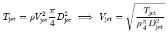
Thrust and yaw-moment loss in forward motion scale with the velocity ratio  , normalizing measured side force
 and yaw moment
 (with lever arm
 from amidships) as7:

To illustrate this velocity-ratio scaling using the TU Delft equation7, consider a 2.0 m tunnel diameter (a standard commercial size paired with ~800–1,150 kW drives in Kongsberg datasheets16, giving area  ) in seawater (
 ) at an illustrative static thrust of 130 kN:

Ship Forward Speed | Speed (m/s) | Illustrative Velocity Ratio (V / Vjet) | Hydrodynamic Flow & Authority Regime |
|---|---|---|---|
0 knots (Static) | 0.00 m/s | 0.000 | Unobstructed transverse jet; effective moment lever arm |
1 knot | 0.51 m/s | 0.081 | Minor downstream jet bending; high lateral thrust |
2 knots | 1.03 m/s | 0.162 | Growing cross-flow deflection and hull suction onset |
3 knots | 1.54 m/s | 0.243 | Upper bound where |
4 knots | 2.06 m/s | 0.324 | Heavy downstream jet deflection and hull suction cancellation |
5 knots | 2.57 m/s | 0.405 | Severe thrust degradation; main rudder hydrodynamic lift takes over7 |
 7
 holds before side force
 drops steeply7
Two coupled fluid mechanisms cause this drop-off7. First, external cross-flow bends the transverse jet aft along the hull plating7. Second, interaction between the deflected jet and external hull flow generates localized low-pressure suction forces on the hull surface downstream of the tunnel outlet—often termed a Coanda-type attachment on stern skegs7—which pulls the hull toward the discharge side and counteracts net sway thrust7. Below roughly 3 knots, the effective yaw lever arm  stays close to
 ; at higher speeds, net side force
 collapses faster than yaw moment
 , making tunnel thrusters largely ineffective for lateral ship movement above 3–5 knots7.
4. SOLAS Redundancy & Single-Failure Criteria
SOLAS Chapter II-1 Regulation 29 establishes deterministic redundancy so that no single hydraulic, piping, or electrical failure renders a ship unsteerable10. Every vessel requires both main and auxiliary steering gear, though ships equipped with two or more identical main power units that together satisfy main steering criteria do not require a separate auxiliary unit10. Tankers, chemical tankers, and gas carriers of ≥10,000 GT, and all other ships of ≥70,000 GT, must carry two or more identical power units10.
For tankers, chemical tankers, and gas carriers ≥10,000 GT, Regulation 29.6 mandates the single-failure criterion: following loss of steering capability due to a single failure in any part of one power actuating system (excluding the tiller, quadrant, or seizure of the rudder actuators), steering capability must be regained within ≤45 seconds10. Vessels comply either via two completely separate power actuating systems (each capable of full 35°-to-30° ≤28 s performance) or via at least two identical interconnected hydraulic actuating systems operating simultaneously that detect hydraulic fluid loss and automatically isolate the failed loop10. Where a single rotary vane actuator is installed on large tankers (such as vessels >100,000 DWT), Kongsberg's IMO-compliant IRV design fulfills single-failure criteria by partitioning two independent power actuating systems using a double hydraulic sealing system inside a single housing55.
In 4-ram interconnected hydraulic installations fitted with a Safematic automatic isolating bypass system, marine engineering training manuals outline the sequential isolation logic following a burst pipe or blown ram seal14:
- First Low-Level Detection (
 ): As oil drains from the leaking loop's reservoir, float switch
 activates audible/visual low-level alarms on the bridge and in the ECR and automatically starts the standby hydraulic pump20.
- Low-Low Level Automatic Isolation (
 ): If leakage continues, float switch
 automatically stops the leaking system's pump and shifts solenoid-operated isolating bypass valves to seal off the damaged cylinder pair (e.g., cylinders 1 & 2) while leaving the healthy pump and opposite cylinder pair (cylinders 3 & 4) pressurized14.
- 45-Second Degraded Recovery: Steering control is automatically restored within ≤45 seconds; operating on two cylinders provides 50% of rated steering torque, requiring speed reduction below half maximum service speed per technical guidance14.
Electrical and alarm architectures provide parallel fault resilience10. Vessels under duplicated rules require two independent bridge steering control circuits separated physically along their cable runs, fed directly from steering power circuits or adjacent switchboard busbars with short-circuit protection only on control supply circuits10. Audible and visual alarms on the bridge and in the ECR alert watchkeepers immediately to power failure, control circuit failure, motor overload, three-phase failure, and low hydraulic oil level so standby units can take over cleanly10. Finally, where rudder stock diameter is 230 mm and above20, Regulation 29 mandates an automatic alternative/emergency power supply—from the emergency switchboard or a dedicated power source inside the steering compartment—energizing a compliant steering power unit, its control loop, and the RAI within 45 seconds for at least 30 minutes on ships ≥10,000 GT or 10 minutes on smaller vessels10.
5. Failure Modes, Testing & Maintenance
Steering and thruster reliability depends on proactive monitoring to catch hydraulic, sealing, and mechanical degradation before transit or harbour maneuvers11.
Hydraulic fluid contamination and air locks represent the most frequent operational threats to electro-hydraulic systems4. Abrasive particles, water ingress, or varnish degrade precision axial-piston swashplate shoes, screw-pump rotors, and pilot/relief valves4. Best-practice marine maintenance schedules specify daily reservoir level checks, weekly low-level alarm verification, quarterly laboratory sampling for ISO 4406 particle counts and moisture, and scheduled filter element changes using OEM-grade oil (e.g., Frydenbø specifies hydraulic oil with viscosity index ~100, or 68 in specific editions, fortified with anti-foam, anti-oxidant, and anti-rust additives)11. SOLAS also mandates a fixed oil storage tank sized to recharge at least one complete actuating system and reservoir10. Whenever hydraulic lines or actuators are opened, air locks compress under load, causing sluggish response, erratic wandering, and hunting; technicians must systematically vent all top actuator and pump bleed plugs4.
Rudder carrier bearing wear and stock/actuator seal leaks gradually erode mechanical alignment and hydraulic stiffness19. Carrier bearings support vertical rudder mass while neck and pintle bearings react radial hydrodynamic loads8; excessive clearance triggers heavy-sea knocking, tiller bushing distress, and stock vibration8. Periodic dry-dock and in-service inspections verify bearing clearances, lubrication schedules, foundation bolt torque, and conical blade-to-stock coupling contact (minimum 70% paint-test contact area under class rules)19. On ram-type actuators, seal wear appears visibly around ram glands and flexible hoses11. On rotary vane units, housing and shaft-gland leaks are external, but internal rotor-vane and dividing-segment seal wear causes concealed internal oil bypass that shows up primarily as extended hard-over times or pressure sag19. On tunnel thrusters, shaft seal integrity is similarly monitored—with Kongsberg TT units allowing drive shaft seal replacement without removing the electric motor and incorporating drain-line seal pressure control for DP service16.
Tunnel thruster blade and grid damage typically arises from ingested ropes, debris, or cavitation/corrosion12. Hydraulic thruster transmissions limit gear damage by relieving impact overloads hydraulically12, whereas geared mechanical units fit rope cutters, skewed blades, and sacrificial anodes13. Although regulatory assessments identify hydrodynamic interactions from protective tunnel grids53, published failure-rate datasets for grid bar fatigue or thruster blade erosion were not available in the reviewed technical sources.
To verify readiness, SOLAS Chapter V Regulation 26 enforces strict pre-departure testing and periodic emergency drills19. Within 12 hours prior to departure (or weekly where short-voyage flag waivers apply, and at least weekly regardless of sailing for tankers, chemical tankers, and gas carriers ≥10,000 GT)19, the crew must execute and log the following checks:
- Operate main and auxiliary steering gear power units separately and combined through full port-to-starboard rudder travel, confirming pressures, temperatures, and slewing times11.
- Test remote steering controls from every bridge position (FU wheel/tiller, NFU levers, and autopilot override), checking random angles to detect feedback deadbands19.
- Verify emergency power supply operation and automatic hydraulic isolating arrangements2.
- Cross-check bridge and steering-flat Rudder Angle Indicators directly against the mechanical rudder-stock pointer11.
- Trigger and confirm audible and visual bridge/ECR alarms for power failure, three-phase failure, motor overload, control failure, and low hydraulic oil level11.
- Perform a thorough visual inspection of steering machinery, linkages, ram glands, flexible hoses, and reservoir oil levels11.
- Test voice communications (hand-powered/sound-powered and automatic telephones) between the bridge and steering gear compartment; departure is unsafe and prohibited under SOLAS compliance rules if communications fail24.
Finally, emergency steering drills must be conducted and logged at least every three months (and within 48 hours before entering U.S. waters per 33 CFR 164.25 unless completed within the preceding three months)19. Drills test local steering control directly from the steering gear compartment, changeover procedures using permanently posted block diagrams, alternative power supplies, and bridge-to-steering-flat command communications2. Annual maintenance additionally verifies gauge calibration and confirms hydraulic relief valves lift at no more than 1.25× design pressure19.
References
- Marine Cybernetics - NTNU, https://assor.folk.ntnu.no/Public/marcyb3%20-%202018.pdf
- Ship Steering Gear: Parts, Types, Modes And SOLAS Rules, https://maritimepage.com/steering-gear-in-ship/
- Numerical Analysis of the Rudder–Propeller Interaction, https://www.researchgate.net/publication/347411561_Numerical_Analysis_of_the_Rudder-Propeller_Interaction
- Steering Gear Modes and Autopilot: Ship Crew Guide - Marine Public, https://www.marinepublic.com/blogs/training/394272-steering-gear-modes-and-autopilot-ship-crew-guide
- Rudder | PDF - Scribd, https://www.scribd.com/document/1000278389/Rudder
- Marine Control System 2 PDF - Scribd, https://www.scribd.com/document/372991670/marine-control-system-2-pdf
- Chapter 9 NON-LINEAR BEHAVIOR - TU Delft OpenCourseWare, https://ocw.tudelft.nl/wp-content/uploads/Part_3.pdf
- Products | Becker Schilling Rudder, https://becker-marine-systems.com/products/manoeuvring-systems/becker-schilling-rudder
- D-21079 Hamburg +49 (0) 40 −2 41 99-0 +49 (0) 40 - WSdot.com, https://wsdot.wa.gov/sites/default/files/2026-08/XE3761_M_3_10031-01_Becker-Rudder-Manual.pdf
- SOLAS Steering Gear Requirements | PDF - Scribd, https://www.scribd.com/document/706880977/IMO-requirements-for-Steering-Gear
- Steering gear SOLAS tests and checks: a guide | HydraulicsUAE, https://hydraulicsuae.com/guides/steering-gear-solas-tests
- Tunnel Thrusters – Hydraulic Pod Motor Driven | Thrustmaster, https://thrustmaster.net/tunnel-thrusters/hydraulic-tunnel-thruster/
- Tunnel Thrusters - ZF, https://www.zf.com/products/en/marine/products_64513.html
- Ship Steering System Overview | PDF | Pump | Valve - Scribd, https://www.scribd.com/document/875976001/Steering-System
- Frydenbö Rotary Vane Steering Gear Manual | PDF | Valve - Scribd, https://www.scribd.com/document/476651044/7717-18
- TUNNEL THRUSTERS TYPE TT FP - Kongsberg, https://www.kongsberg.com/contentassets/f5b6d4fd72884224a0f7c01ee5a2d4f5/03.tunnel_4p_06.05.11.pdf
- Understanding the difference between FU and NFU steering, https://as-scan.com/info/the-as-scan-blog/understanding-the-difference-between-fu-and-nfu-steering
- SAC1100 tunnel thruster Ø513mm 400V low harmonic, IP55 - Sleipner, https://www.sleipnergroup.com/thruster-systems/thrusters/sac1100-tunnel-bow-stern-thruster-o513mm-400v-l-h
- Steering Gear Maintenance and Testing: SOLAS Requirements for, https://marineinspection.app/article/steering-gear-maintenance-testing-solas-requirements-ships
- Steering Gear Requirements Overview | PDF | Safety | Ships - Scribd, https://www.scribd.com/document/414520417/Safe-Matic
- Maintenance Manual Kongsberg Steering Gear type SR and SV, https://cdn.prod.website-files.com/66cd8cdddc44806a528df773/67a0c3b9a9e08a9aa10ccf97_Maintenance%20Manual%20SR%20&%20SV%20Steering%20Gear.pdf
- Ship's Steering Gear: How It Works, Diagram & Examples | FIRGELLI, https://www.firgelliauto.com/blogs/mechanisms/ship-s-steering-gear
- Istamar Shipping Brokering Ind & Trad Ltd., http://www.istamar.com/
- Steering Gear Tests, Procedures & Emergency Drills - Marine Public, https://www.marinepublic.com/blogs/training/797284-steering-gear-tests-procedures-emergency-drills
- SOLAS V and Steering Gear - Navsregs, https://navsregs.wordpress.com/2017/11/24/solas-v-and-steering-gear/comment-page-1/
- Maritime Safety and Certification Guide | PDF | Special Drawing Rights, https://www.scribd.com/document/487223880/surveyor-oral-questions
- SOLAS 1974 Interpretations Guide | PDF | Oil Tanker | Ships - Scribd, https://www.scribd.com/document/489911583/UI-SC-pdf2740-pdf
- Merchant Shipping Notice 1907 - Legislation.gov.uk, https://www.legislation.gov.uk/uksi/2023/246/pdfs/uksiod_20230246_en.pdf
- Steering gear - Mechanical Engineering, http://mh-mechanicalengineering.blogspot.com/2012/06/steering-gear.html
- ALL IN ONE - Sanger Met, https://sangermet.com/dane/pliki/42/85/4285e2f40488e38/hatlapa_all_in_one_2012_web_res_single_pages.pdf
- Steering Gear in Ship Working, Types, Diagram, Regulations, https://marinerspointpro.com/steering-gear-in-ship/
- PORSGRUNN Steering Gear - MacGregor, https://www.macgregor.com/globalassets/picturepark/imported-assets/56943.pdf
- Tenfjord Steering Gear Spare Parts Supplier - Vessel Core, https://vesselcore.eu/tenfjord-steering-gear-parts
- Marine Steering Gear Systems Overview | PDF - Scribd, https://www.scribd.com/document/496454202/Chapter-1-Steering-Gear
- Geometric characteristics of the full spade rudder compared with the, https://www.researchgate.net/figure/Geometric-characteristics-of-the-full-spade-rudder-compared-with-the-semi-balanced-rudder_fig2_264067831
- Numerical Investigation of Coupled Oblique Flow and Steering, https://www.mdpi.com/2077-1312/13/11/2140
- measurements and calculations of gate rudder performance, https://www.gatersproject.com/publications/measurements-and-calculations-of-gate-rudder-performance-amt17.pdf
- Chapter 5 - Aerodynamics of Flight - Federal Aviation Administration, https://www.faa.gov/sites/faa.gov/files/07_phak_ch5_0.pdf
- Analysis of propeller slipstream effects - ICAS ORG, https://www.icas.org/icas_archive/ICAS1996/ICAS-96-4.10.3.pdf
- Products | Becker Flap Rudder, https://becker-marine-systems.com/products/manoeuvring-systems/becker-flap-rudder
- Rudder - Wärtsilä, https://www.wartsila.com/encyclopedia/term/rudder
- SEMI-SPADE RUDDER VS. FULL SPADE ... - Becker Marine Systems, https://login.becker-marine-systems.com/01_news/zzpdf/newsletter_27.pdf
- Types of Ship Rudders, Their Parts, and Steering Profiles, https://captainsmode.com/types-of-ship-rudders/
- BECKER FLAP RUDDER, https://becker-marine-systems.com/fileadmin/redakteure/bilder/Company/Media/Downloads/Product_brochures_NEW/2.1_Becker_Flap_Rudder.pdf
- Chapter 10 HULL OUTFITTING Section 1 RUDDER AND ... - ClassNK, https://www.classnk.or.jp/hp/pdf/rules/amendments/e-Amendments/06.03.20/CSR-B/14_Chapter10.pdf
- Becker Flap Rudder PDF - Scribd, https://www.scribd.com/document/388403047/BECKER-FLAP-RUDDER-pdf
- Station keeping with High-Performance Rudders, https://dynamic-positioning.com/proceedings/dp2012/design_control_mehldau.pdf
- Becker Schilling rudder - Bövik Marin AB, https://shop.bovikmarin.se/en/agencies-and-brands/commercial-marine-shipyards-offshore/becker-marine-systems/rudders-from-becker-marine-systems/becker-schilling-rudder/
- flap rudder for ships - Becker Marine Systems - Catalogs Nauticexpo, https://pdf.nauticexpo.com/pdf/becker-marine-systems/flap-rudder-ships/30793-9264.html
- FPP Bow Tunnel Thruster - Hi-Sea Marine, http://www.hiseamarine.com/fpp-bow-tunnel-thruster-3743.html
- Long Tunnel Configurations for High Efficiency Thrusters, https://www.marinepropulsors.com/proceedings/2017/THA2-2.pdf
- Control of Marine Propellers - NTNU, https://assor.folk.ntnu.no/PhD%20Thesis/Smogeli_PhD_Thesis.pdf
- Ship Stability Questions and Concepts | PDF | Watercraft - Scribd, https://www.scribd.com/document/970863638/QUESTION-BOOKLET
- 16th Symposium on High-Performance Marine Vehicles - HIPER, http://data.hiper-conf.info/Hiper2024_Drubeck.pdf
- Maintenance Manual Frydenbö IRV-4 Steering Gear, https://cdn.prod.website-files.com/66cd8cdddc44806a528df773/67a0c3ba4ed06d10ad6cb101_Maintenance%20Manual%20IRV4%20Steering%20Gear.pdf
- Frydenbö Steering Gear Instruction Manual | PDF | Valve - Scribd, https://www.scribd.com/document/715756014/steering-gear
- ulstein steering gear manual, https://maritimeexpert.wordpress.com/wp-content/uploads/2016/08/ulstein-steering-gear-manual.pdf
- SOLAS Ch. V Reg. 26 - Steering gear: testing and drills - imorules, https://www.imorules.com/GUID-D53FC09F-63E6-4632-AB96-87D116DAE9E6.html
- CHIEF ENGINEER Unit 3 SOLAS Q1 - SVE Study, https://svestudy.com/?page_id=8067
- SOLAS Chapter I: Ship Maintenance Guidelines | PDF - Scribd, https://www.scribd.com/document/786756986/MARLAW-MIDTERM