Part 1: System cardDel 1: Systemkort
1. Core Function
Marine LNG reliquefaction systems capture natural Boil-Off Gas (BOG) evaporating from cryogenic cargo tanks stored near -162°C to -163°C due to ambient heat ingress1. By compressing BOG and rejecting heat through closed-loop refrigeration cycles or high-pressure expansion cycles, these plants re-condense methane-rich vapor into liquid LNG and return it to the cargo tanks2. This continuous recovery loop keeps tank pressure within design limits below structural relief settings without venting cargo to the atmosphere or wasting excess gas through combustion3.
2. Primary Operational Tasks
- Cargo Tank Pressure Regulation: Extract vapor at controlled rates to maintain tank pressure within design limits and safely below the Maximum Allowable Relief Valve Setting (MARVS) across laden and ballast voyages3.
- Low-Speed and Idle BOG Recovery: Re-condense excess vapor whenever evaporation outpaces propulsion demand—such as during reduced-speed transit, idle periods, or bunkering and loading operations—preserving cargo volume2.
- Nitrogen Separation and Composition Control: Strip non-condensable nitrogen (0–30 mol% in BOG) in downstream phase separators and switch to partial-reliquefaction or vent-gas modes as cargo composition shifts (engine methane-number tuning metrics are not detailed in available sources)3.
- Excess Gas Thermal Oxidation Backup: Divert non-condensable off-gas or pressure-surge BOG to a Gas Combustion Unit (GCU) or dual-fuel engines during reliquefaction plant trips or rapid tank pressure rises3.
- Cargo Conditioning and Holding-Time Extension: Return reliquefied LNG to cargo tank bottoms to keep containment spaces cold and extend holding times on ballast voyages with minimum heel4.
3. System Interconnections
- Inputs: Cryogenic BOG from cargo tank vapor headers (-100°C to -130°C at compressor suction)2; shipboard electrical power feeding compressor/compander motors (ranging from low-voltage integrated drives on compact skids to ~5.2 MW companders on Q-Max carriers) alongside Variable Frequency Drive (VFD) and Active Magnetic Bearing (AMB) cabinets (specific high-voltage main switchboard bus details are not specified in available sources)4; seawater/cooling-water circuits designed for 32°C IMO upper sea limits (up to 36°C process cooling-water specs; dedicated central freshwater loop layouts are not detailed in available sources)5; tank pressure and temperature sensors3; and Integrated Automation System (IAS) setpoints and mode selections (specific PLC hardware and Cargo Control Room panel architectures are not detailed in available sources)3.
- Outputs: Reliquefied liquid LNG returned to cargo tank bottoms (leaving the cold box near -159.5°C in a representative full-reliquefaction cycle; exact subcooling margins below tank saturation are not specified in available marine datasheets)3; non-condensable nitrogen-rich vapor vented to the GCU or vent mast3; excess BOG diverted to the GCU or dual-fuel consumers3; and control, alarm, monitoring, and safety shutdown signals, including burner flame-failure shut-offs and compressor/expander trips (explicit tank high-pressure trip setpoint schedules are not detailed in available sources)3.
4. Redundancy & Criticality
Under Chapter 7 of the IMO International Code for the Construction and Equipment of Ships Carrying Liquefied Gases in Bulk (IGC Code, Resolution MSC.370(93)), cargo tank pressure and temperature must remain within design limits at all times—below MARVS—through reliquefaction, thermal oxidation (approved solely for LNG with no externally visible flame and exhaust strictly below 535°C), pressure accumulation, or liquid cooling, with atmospheric venting prohibited except in emergencies (Sections 7.1, 7.2, 7.4)5. Total capacity must accommodate upper ambient design temperatures of 32°C seawater and 45°C air (Section 7.2)5. The IGC Code Chapter 7 excerpts reviewed here do not contain the explicit prescriptive subclauses governing standby-train redundancy; in commercial carrier practice (such as Q-Flex/RG3 vessels), full-reliquefaction plants install dual 100%-capacity BOG compressors backed by a GCU3. On LNG-fueled non-carrier vessels governed by the IGF Code (Resolution MSC.391(95), Section 6.9), routine gas discharge to the atmosphere is likewise prohibited, though fuel containment systems such as Type-C tanks may employ calculated pressure-accumulation holding times of up to 15 days while idle7.
Part 2: Technical deep diveDel 2: Teknisk dybdeanalyse
1. Boil-Off Gas (BOG) Thermodynamics & Cryogenic Tank Pressure Control
Liquefied natural gas is carried near atmospheric pressure at approximately -162°C to -163°C, achieving a liquid-to-gas volume reduction ratio of roughly 1:6001. Even across thick cryogenic barriers, conduction, convection, and radiation continuously transfer heat from ambient air (IMO upper design 45°C) and seawater (32°C) into the cargo1. Because the stored LNG sits at its saturation boiling point, incoming thermal energy converts directly into latent heat of vaporization (H_vap = 511 kJ/kg at -162°C and 1 bar)1:
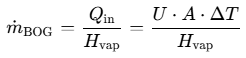
Here, Qin is the total hull and penetration heat flow determined by the overall heat transfer coefficient U, tank surface area A, and external-to-cargo temperature difference ΔT (~180–183°C under typical hull conditions, reaching up to 207°C against IMO's 45°C upper air design limit)1. As saturated vapor rises through the tank ullage and unsubmerged vapor headers, superheating warms the BOG to roughly -100°C to -130°C prior to entering the reliquefaction compressor suction2.
Containment geometry and insulation thickness govern the daily Boil-Off Rate (BOR), expressed as the percentage of cargo volume or initial loaded mass evaporating every 24 hours1. Hull-integrated membrane designs capture approximately 80% of the LNG carrier fleet due to superior space utilization—vendor literature reports ~15% (NO96) to ~18% (Mark III) higher cargo capacity than spherical tanks on comparable hulls26, while academic comparisons report >8% higher cargo loading27—whereas self-supporting Moss aluminum spheres rest independently on equatorial skirts22. Thickening insulation directly suppresses heat ingress: on a 160,000–170,000 m³ vessel, upgrading GTT Mark III insulation from 270 mm to 400 mm reduces commercial BOR by 0.05%/day, preventing 85 m³ (36 tonnes/day) of evaporation28. Applying the 511 kJ/kg latent heat benchmark1 shows this 36 t/day (0.417 kg/s) reduction eliminates ~213 kW of continuous thermal ingress; scaling linearly on the same 170,000 m³ basis to a 0.07%/day Mark III Flex+ guarantee28 gives ~50.4 t/day of boil-off, or ~298 kW of total latent heat load.
Containment System | Primary Barrier & Structural Geometry | Insulation & Secondary Arrangement | Typical / Guaranteed BOR (% V/day) | Representative Design / Working Pressure |
|---|---|---|---|---|
GTT Mark III (Standard) | Corrugated SS304L (1.2 mm), hull-integrated prismatic22 | 270 mm (100 + 170 mm) R-PUF foam (130 kg/m³) + composite secondary membrane1 | 0.125%–0.15% (170k m³)28 | 0.7 barg typical membrane MARVS30 |
GTT Mark III Flex / Flex+ | Corrugated SS304L (1.2 mm), modified pump/gas domes28 | 400 mm (Flex) / 480 mm (Flex+) R-PUF panels28 | 0.085%–0.10% (Flex); 0.07% (Flex+)28 | 0.7 barg typical membrane MARVS30 |
GTT NO96 | Invar (36% nickel alloy, 0.7 mm)22 | Plywood boxes filled with perlite, secondary barrier, N₂-purged space1 | 0.10% (modern); 0.085% (evolved 174k m³)22 | 0.7 barg typical membrane MARVS30 |
Moss Spherical | Self-supporting Al-5083 spheres on equatorial skirt (~500–600 mm contraction)22 | Exterior sprayed polyurethane foam22 | 0.20%–0.25% (1970s); 0.15%–0.20% (modern/improved)22 | ~22 kPa (3.2 psi / 0.22 bar) working pressure, adjustable32 |
Independent numerical modeling and reduced-order analysis by Miana et al. on a 165,000 m³ Mark III carrier (at 98% fill) yields slightly lower theoretical U values than vendor guarantees: 0.0674 W/(m²·°C) at 270 mm (BOR 0.0919%/day) dropping to 0.0453 W/(m²·°C) at 400 mm (BOR 0.0631%/day)1. Across commercial LNG carriers, aggregate BOG mass flow spans 2,000–11,000 kg/h, reaching 5–6 t/h on 200,000 m³ vessels at 0.15% BOR and ~7 t/h on 266,000 m³ Q-Max ships2.
To hold tank pressure within operating limits, pressure transmitters monitor ullage trends and signal the ship's Integrated Automation System (IAS) to modulate centrifugal BOG compressor capacity via Diffuser Guide Vanes (DGVs)3. Rising tank pressure alongside increasing compressor load and DGV opening warns that reliquefaction capacity is nearing saturation, triggering automatic gas diversion to dual-fuel consumers or the GCU; falling tank pressure signals excess vapor extraction, prompting DGV turndown3. Uncontrolled pressure escalation forces tank ullage pressure toward MARVS5. Under IGC Code Chapter 8 (1993/2003 supplement), pressure relief valves (PRVs) must activate at or below MARVS (though when multiple PRVs are installed, valves totaling up to 50% of total relieving capacity may be set up to 5% above MARVS), inlet vent-line pressure drop cannot exceed 3% of set pressure, and fire-exposure discharge backpressure on unbalanced PRVs must not exceed 10% of gauge inlet pressure34. Lifting PRVs releases flammable methane (4%–14% flammability range in air) across vent risers positioned at least B/3 or 6 m above the weather deck, generating hazardous gas zones extending 6 m radially around and below the outlet while violating IGC 7.1.3 anti-venting rules and IGF zero-discharge requirements5.
2. Reverse Brayton Nitrogen Cycle vs. Mixed-Refrigerant Systems
Full-reliquefaction plants decouple cargo pressure control from main engine load, allowing carriers to operate at any vessel speed without flaring cargo3. Two closed-loop refrigeration architectures dominate marine full-reliquefaction installations: the Reverse Brayton Nitrogen (N₂) Cycle and Mixed-Refrigerant (MR) / Cascade loops4.
In the Reverse Brayton N₂ cycle—deployed in Wärtsilä/Hamworthy Moss RS and Mark III systems, Wärtsilä Compact Reliq, Cryostar EcoRel, and Air Liquide Turbo-Brayton units—cargo vapor undergoes combined compression and condensation as defined in IGC Code Section 7.3.1.35. On the process side, BOG is compressed across BOG compressors (4.5 bar discharge in earlier Hamworthy Moss RS units; 4.5–22 bara BOG handling range in Wärtsilä Compact Reliq specifications)9. Vendor documentation for Wärtsilä's third-generation Mark III system reports that adding an extra compressor stage raises BOG condensation pressure and temperature while rejecting compression heat earlier in the cycle, lowering power consumption by roughly 15%10. Compressed BOG then enters a cryogenic plate-fin heat exchanger (cold box), condensing near -159.5°C in representative full-reliquefaction operation3.
Refrigeration duty is provided by a closed circuit of commercial-grade gaseous nitrogen—non-flammable, inert, and cargo-compatible per IGC 7.3.25. In a representative Hamworthy Moss RS process, N₂ enters a 3-stage centrifugal compressor at 13.5 bar and discharges at 57 bar with water-cooled inter- and aftercooling9. High-pressure warm N₂ is pre-cooled in the cold box before expanding across a shaft-coupled cryogenic turbo-expander (compander), recovering work while chilling the nitrogen below LNG condensation temperature3. Although nitrogen condenses at 88 K under 3 atm pressure, Reverse Brayton marine cycles maintain N₂ as a single-phase gas throughout the loop, removing BOG latent heat via sensible gas warming before returning to compressor suction4. Smooth capacity turndown from 100% to near 0% is achieved by varying loop N₂ inventory from a buffer reservoir alongside VFD speed and DGV control3.
By contrast, Single Mixed-Refrigerant (SMR) plants operate on an inverse Rankine vapor-compression cycle in which a tailored multi-component refrigerant blend evaporates inside a single Main Cryogenic Heat Exchanger (MCHE) to chill and liquefy gas36. Cascade systems instead condense primary vapor against an evaporating secondary refrigerant at lower temperatures, trading increased mechanical and control complexity (multiple compressors, heat exchangers, and coordinated control circuits) for multi-cargo temperature flexibility15. Wärtsilä introduced marine MR reliquefaction plants rated at 1.5–2.5 t/h for LNG carriers37 and reports <0.75 kWh/kg power consumption in a vendor press release for an onshore bioLNG MR liquefaction module alone41.
Evaluating thermodynamic Coefficient of Performance (COP = Q_refrig / P_elec) from Wärtsilä Compact Reliq vendor specifications (36°C cooling water, pure methane) highlights the impact of BOG inlet pressure11: for a baseline CRS unit liquefying 850 kg/h at 1.02 kWh/kg ("kW/kg" in datasheet, matching the 800–900 kW electrical rating in8), electrical draw is 850 × 1.02 = 867 kW against 133 kW cooling duty, giving a COP of 0.153. Adding a BOG booster (CRS+ at 1,500 kg/h, 234 kW duty, 0.59 kWh/kg) requires 1,500 × 0.59 = 885 kW and lifts COP to 0.264—a 42% cut in specific energy11. No independent peer-reviewed marine sea-trial benchmarking commercial shipboard SMR versus Reverse Brayton plants under identical operating profiles was found in the reviewed sources; available benchmarks trace to vendor specifications and academic cycle analyses.
Engineering Parameter | Reverse Brayton Nitrogen (N₂) Cycle | Single Mixed-Refrigerant (SMR) / Cascade |
|---|---|---|
Thermodynamic Cycle | Closed gas-phase reverse Brayton with work-recovering turbo-expander9 | Inverse Rankine phase-change cycle in MCHE (SMR) or coupled stages (cascade)15 |
Working Fluid | Commercial-grade inert N₂; avoids phase-change composition drift4 | Multi-component refrigerant blend (SMR) or secondary refrigerants (cascade)15 |
Specific Power Benchmarks | ~0.74 kWh/kg compander-only duty on 7 t/h Q-Max (~5.2 MW, Cryostar)12; 0.59–1.12 kWh/kg (Wärtsilä Compact Reliq)11; 0.7 kWh/kg cited in academic overview42 | <0.75 kWh/kg (Wärtsilä onshore bioLNG MR unit alone)41; 1.5–2.5 t/h marine MR plants deployed37 |
Load Turndown & Dynamics | Near 0%–100% automated turndown via N₂ inventory and VFD/DGV control3 | Higher control complexity across coupled refrigerant circuits in cascade layouts15 |
Marine Risk & Maintenance | Oil-free magnetic bearings; avoids unstable refrigerant mix and oil-separator failures4 | Relies on refrigerant blend stability and oil/refrigerant management; IGC 7.3.2 compatibility constraints4 |
3. Partial Reliquefaction (PRS) & Subcooling Systems
Replacing steam turbines with high-efficiency slow-speed two-stroke dual-fuel propulsion drastically reduced onboard BOG consumption, leaving excess boil-off gas whenever engines operate below peak demand9. High-pressure ME-GI engines deliver 48%–50% thermal efficiency22, while PRS academic literature models both ~300 bar high-pressure gas-injection supply systems (ME-GI class) and modified 16 bar medium-pressure gas-engine configurations (X-DF class)11. Because these vessels already carry multistage BOG fuel compressors, Partial Reliquefaction Systems (PRS) divert surplus high-pressure compressed BOG into a regenerative self-cooling loop, liquefying excess vapor without installing a dedicated external nitrogen or mixed-refrigerant plant2.
In a typical PRS architecture, cold tank BOG (-100°C to -130°C) passes through a regenerative cryogenic heat exchanger (LNG-100 in exergy studies) before entering the multistage fuel-gas compressor2. After compression up to ~300 bar (on high-pressure ME-GI loops), the surplus gas not burned by the main engine routes back through the warm pass of the cryogenic heat exchanger, rejecting heat to cold incoming tank BOG and recycled flash vapor2. The chilled high-pressure gas then expands across a decompression expansion valve (operating via Joule-Thomson throttling) down to near-atmospheric pressure, producing a two-phase saturated liquid-vapor mixture inside a separator2. Condensed liquid LNG flows back to the cargo tanks, while cold separated flash gas recycles through the heat exchanger to supplement cooling duty and return to compressor suction2.
Exergy optimization comparing 300 bar PRS designs against modified 16 bar configurations demonstrates that discharge pressure prior to the expansion valve strongly governs parasitic recycle power: increasing final compressor discharge pressure reduces the uncondensed recycle gas fraction, whereas dropping below 150 bar causes recycled vapor flow to dominate total compressor power demand43. Preserving cold vapor quality in deck headers is equally critical: GTT estimates across PRS, Full Reliquefaction (FRS), and Advanced PRS (A-PRS) arrangements indicate that keeping BOG up to 12°C colder at system entry increases liquefaction capacity by 6%–12% for PRS and 4%–7% for FRS13. Where vessels require higher capacity or operational independence from engine fuel-compressor pressure, compact external booster skids—such as Wärtsilä's Compact Reliq Single Booster (CRSB, rated 0.59–0.64 kWh/kg in datasheet CRS+ configurations)—supplement onboard handling11. Related onshore end-flash liquefaction analyses by Air Products illustrate the underlying flash-drum physics: warmer heat-exchanger exit temperatures shift refrigeration load onto flash gas recovery, generating 65%–75% adiabatic flash vapor when feed nitrogen stays at or below 1 mol%45.
4. Cryogenic Companders, Cold Boxes & Nitrogen Stripping
Modern Brayton reliquefaction skids center mechanically on a high-speed cryogenic compander combining multi-stage centrifugal compressor wheels and a radial turbo-expander on one shaft with a hermetically sealed, VFD-driven electric motor4. On large Q-Max carriers (~7 t/h BOG), Cryostar EcoRel companders require ~5.2 MW of shaft power12. Newer modular designs replace oil-lubricated bearings with Active Magnetic Bearings (AMBs) inside a hermetic casing, completely eliminating gearboxes, lubricating-oil systems, and external shaft seal-gas loops4. Per Wärtsilä Compact Reliq vendor documentation, oil-free AMB construction eliminates scheduled rotating maintenance between five-year drydockings and extends major compressor overhaul intervals to ten years4. Operational reliability nonetheless hinges directly on expander availability: a compressor or N₂ expander trip immediately halts refrigeration capacity and stops BOG condensation3.
Heat exchange between compressed BOG and cold N₂ occurs inside multi-stream plate-fin cryogenic heat exchangers (PFHEs) housed within an insulated cold box, condensing methane-rich vapor down to roughly -159.5°C3. Keeping cryogenic vessels and downstream piping permanently cold avoids repeated thermal cool-down phases and minimizes flash losses (a practice documented in onshore liquid-nitrogen phase-separator operations47), while marine reliquefaction skids rely on dynamic-simulator-tuned control systems to manage startup and load transients8. Specific PFHE brazed-aluminum metallurgical criteria and quantitative cool-down rate limits (such as allowable °C/h thermal-shock gradients) were not present in the available sources and must be obtained from cold-box OEM manuals.
Because nitrogen boils at -196°C—roughly 34°C lower than LNG (~-162°C)—it evaporates preferentially from cargo tanks1. Although loaded LNG typically carries ≤0.5%–1% nitrogen11, preferential boil-off enriches vapor-header BOG across a 0–30 mol% N₂ range9. Left unseparated, non-condensable nitrogen accumulates on cold-box surfaces and inhibits condensation. Reliquefaction trains therefore discharge condensed two-phase output into a flash-gas / phase separator (operating around 4.5 bar in Hamworthy Moss RS systems)3. Liquid LNG drains from the separator bottom back to cargo tank bottoms via differential pressure, while non-condensable N₂-rich gas vents overhead to the GCU (satisfying IGC 7.3.1.4 to avoid atmospheric methane venting where reasonably practicable) or vent mast4. When BOG nitrogen content exceeds ~12 mol%, switching to partial-reliquefaction or vent-gas mode—routing the N₂-rich stream to the GCU rather than attempting total condensation—substantially reduces compressor power while maintaining tank pressure control3. While external reliquefaction prevents nitrogen accumulation in the loop4 and multi-component volatility shifts govern phase behavior during evaporation and condensation15, empirical shipboard studies linking subcooled bottom-return stratification directly to cargo aging or tank rollover were not present in the available documentation.
5. Failure Modes, Dry-Gas Seals & Emergency GCU Backup
Continuous cryogenic reliquefaction faces distinct mechanical and process-fouling hazards. On conventional non-hermetic centrifugal BOG compressors, dry-gas seals (DGS) use a non-contacting gas film to isolate rotating shafts and prevent cargo-gas escape48. Reliable sealing requires clean seal gas, stable differential pressure, and continuous leak-off monitoring48. During transient upsets or dry seal-gas starvation, seal faces risk physical contact and performance degradation unless built with contact-tolerant materials (such as John Crane's vendor-tested Carbon LF on Type 28XP seals, which demonstrated steady leakage across contacting test regimes)49. Hermetically sealed AMB companders eliminate this seal-failure mode altogether by removing shaft penetrations and seal-gas subsystems4.
Two internal fouling mechanisms threaten cryogenic cold boxes: component freeze-up and lube-oil carryover. Specific component freeze-up thresholds (such as water-vapor ppm limits for gas hydrates or CO₂ dry-ice precipitation curves) and field blockage frequencies inside marine PFHE cold boxes were unavailable in the reviewed sources; however, Wärtsilä technical documentation explicitly identifies heavy hydrocarbon freezing inside recondensers as an operational blockage risk—a hazard reduced when reliquefying lighter vapor-phase BOG, which carries fewer heavy hydrocarbons than bulk liquid LNG4. Similarly, oil-lubricated compressors and geared drives depend on oil-separation systems that vendor documentation flags as "prone to failure, unstable refrigerant mix or maintenance"—a failure vector eliminated by oil-free magnetic-bearing companders4 (empirical heat-transfer fouling rates from oil carryover were not detailed in available sources).
When mechanical faults or surge loads exceed reliquefaction capability, the Gas Combustion Unit (GCU) provides the primary safety backstop3. Because cryogenic loops respond more slowly than gas burners, automated ship controls divert BOG to the GCU during: (1) sudden BOG compressor or N₂ expander trips, (2) rapid tank pressure climbs exceeding compressor DGV capacity, and (3) continuous disposal of N₂-rich separator off-gas3. Under IGC Code Section 7.4, thermal oxidation is authorized exclusively for LNG cargoes under strict safety requirements6: uptake exhaust temperatures must remain strictly below 535°C with no externally visible flame6; each unit must feature a dedicated forced-draught system and separate uptake designed to prevent gas accumulation6; and burner safety interlocks must block gas flow until ignition is established, trigger automatic shut-off upon flame failure, permit accessible manual isolation, and automatically purge burner gas-supply piping with inert gas once extinguished6.
Failure Mode / Hazard | Root Physical Mechanism | Key Diagnostic Indicators | Engineering Safeguard & Emergency Backup |
|---|---|---|---|
Dry-Gas Seal (DGS) Degradation | Seal-gas starvation or dry contact causing seal-face degradation on external-drive compressors48 | Seal-gas quality/ΔP loss, abnormal leak-off behavior48 | Contact-tolerant Carbon LF seal faces49, leak-off monitoring48, or seal-less hermetic AMB companders11 |
Cold Box Freezing / Plugging | Heavy hydrocarbon freezing in recondensers (hydrate / CO₂ solidification thresholds unverified in available sources)4 | Impaired condensation / recondenser blockage (specific PFHE ΔP/ΔT alarm thresholds not detailed in available sources)4 | Reliquefying lighter vapor-phase BOG (fewer heavy ends)4, GCU bypass during upsets3 |
Lube-Oil Carryover Fouling | Failure-prone oil-separation components contaminating oil-lubricated loops4 | Oil-separator failures and unstable refrigerant mix4 | Oil-free Active Magnetic Bearings (AMBs) and integrated hermetic rotors4 |
Compander / Expander Trip & Surge Pressure | Sudden loss of N₂ expansion refrigeration or rapid tank pressure rise outpacing loop ramp rate3 | Compressor/expander trip or rising tank pressure alongside rising BOG compressor load / DGV position3 | Instant automatic fail-over to GCU (<535°C exhaust, dedicated forced draught, auto inert-gas purge)3 |
References
- (PDF) Calculation of Boil-Off Rate of Liquefied Natural Gas in Mark, https://www.researchgate.net/publication/283990881_Calculation_of_Boil-Off_Rate_of_Liquefied_Natural_Gas_in_Mark_III_tanks_of_ship_carriers_by_numerical_analysis
- Partial reliquefaction system of Boil-Off-Gas for a ship - Google Patents, https://patents.google.com/patent/KR20170107265A/en
- LNG Full Reliquefaction Plant Explained, https://lngnavigator.eu/lng-full-reliquefaction-plant-explained/
- Compact Reliq - Wärtsilä, https://www.wartsila.com/docs/default-source/marine-documents/events/kormarine/kormarine-2021/compact-reliq.pdf?sfvrsn=82c67d43_3
- Chapter 7 — Cargo Pressure/Temperature Control - imorules, https://www.imorules.com/GUID-14784E18-EFAB-4BE5-839E-66B862C90185.html
- RESOLUTION MSC.370(93) (adopted on 22 May 2014, https://wwwcdn.imo.org/localresources/en/KnowledgeCentre/IndexofIMOResolutions/MSCResolutions/MSC.370(93).pdf
- From Flammability to Toxicity: A Comparative Regulatory Analysis of, https://www.mdpi.com/2227-9717/14/9/1387
- Compact Reliquefaction Unit - Wärtsilä, https://www.wartsila.com/docs/default-source/marine-documents/events/kormarine/wartsila-compact-re-liquefaction-unit.pdf
- LNG Reliquefaction Systems Overview | PDF | Liquefied Natural Gas, https://www.scribd.com/document/67144088/regasification-Hamworthy
- LNG Reliquefaction System - Wärtsilä, https://www.wartsila.com/encyclopedia/term/lng-reliquefaction-system
- Compact Reliq Bog Reliquefaction | PDF | Liquefied Natural Gas, https://www.scribd.com/document/771345112/compact-reliq-bog-reliquefaction
- special report - Cryostar, https://cryostar.com/datas-pdf/magazine/cryostar_magazine10.pdf
- BOG Line - A simple lever to improve energy efficiency of PRS, FRS, https://www.gtt.fr/bog-line-simple-lever-improve-energy-efficiency-prs-frs-and-prs
- Wärtsilä LNG Systems - ShipServ, https://www.shipserv.com/ShipServ/pages/profiles/83172/documents/brochure-offshore-lng-systems.pdf
- Gas Carrier Reliquefaction Systems: Technology & Operations Guide, https://www.marinepublic.com/blogs/oil-and-gas/786385-gas-carrier-reliquefaction-system-technology-operation-guide
- LNG Bunkering: Technical and Operational Advisory, https://superlng.adrioninterreg.eu/wp-content/uploads/2020/04/2_FILE.pdf
- RESOLUTION MSC.391(95) (adopted on 11 June 2015), https://www.liscr.com/marketing/liscr/media/liscr/online%20library/maritime/Res-MSC-391(95).pdf
- LNG Fuel Handling and Safety Manual | PDF | Liquefied Natural Gas, https://www.scribd.com/document/565564259/THUN-EOS-Fuel-Handling-Manual
- (PDF) Method of type-C liquefied natural gas tank modeling based, https://www.researchgate.net/publication/372338298_Method_of_type-C_liquefied_natural_gas_tank_modeling_based_on_volume_optimization_for_future_milk-run_exploitation
- RESOLUTION MSC.391(95) (adopted on 11 June 2015), https://wwwcdn.imo.org/localresources/en/KnowledgeCentre/IndexofIMOResolutions/MSCResolutions/MSC.391(95).pdf
- ABS LNG Bunkering Technical and Operational Advisory, https://ww2.eagle.org/content/dam/eagle/advisories-and-debriefs/ABS_LNG_Bunkering_Advisory.pdf
- LNG Carriers: How LNG Ships Work, Sizes & Tank Types, https://liquefiednaturalgas.org/technology/shipping/
- LNG Carrier Containment: Moss Tanks vs Membrane Design, https://offshoreindustry.co.uk/lng-carrier-cargo-containment-systems-moss-spherical-tanks-membrane-design-and-the-engineering-of-cryogenic-transport/
- LNG SHIPS - Marine Study, https://marinestudy.net/lng-ships/
- Moss Type LNG Carriers: Complete Technical Guide, https://lngnavigator.eu/moss-type-lng-carriers/
- Marine Division | Inocrete Corporation, https://www.inocrete.co.jp/english/marine.html
- Comparison of Spherical and Membrane Large LNG carriers in, https://pure.kaist.ac.kr/en/publications/comparison-of-spherical-and-membrane-large-lng-carriers-in-terms-/
- Mark III technologies | GTT, https://www.gtt.fr/activities/gtt-energy/technologies-expertise/membranes/markiii
- DNV Qualified Mark III FLEX System to Reduce Boil-Off Rate (Norway), https://www.offshore-energy.biz/2012/10/09/dnv-qualified-mark-iii-flex-system-to-reduce-boil-off-rate-norway
- Approval in Principle (AiP) from DNV for membrane tanks with ... - GTT, https://www.gtt.fr/approval-principle-aip-dnv-membrane-tanks-design-vapour-pressure-2-barg
- THE MARCH OF THE GTT MEMBRANE, https://www.gtt.fr/sites/default/files/lng_may18_containment_systems.pdf
- Watch: LNG Ship Operations Explained - Marine Insight, https://www.marineinsight.com/watch-lng-ship-operations-explained/
- NO96 technologies - GTT, https://www.gtt.fr/activities/gtt-energy/technologies-expertise/membranes/no96
- International Code for the Construction and Equipment of Ships, https://wwwcdn.imo.org/localresources/en/publications/Documents/Supplements/English/IGC_2003sup.pdf
- Cool concepts handle LNG boil-off - News Content Hub - Riviera, https://www.rivieramm.com/news-content-hub/news-content-hub/cool-concepts-handle-lng-boil-off-52698
- UNECE WPG LNG Chapter 2, https://unece.org/DAM/energy/se/pdfs/wpgas/session/1st_Session_Group_Experts_on_gas/2_-_Chapter_2_LNG_Study.pdf
- Wärtsilä to provide re-liquefaction plants for three new LNG carriers, https://www.ship-technology.com/news/newswrtsil-to-provide-re-liquefaction-plants-to-three-new-lng-carriers-5915365/
- Air Liquide - Understanding the Turbo-Brayton technology - YouTube, https://www.youtube.com/watch?v=nnvROCJdfkk
- Applied Second Law Analysis of Heat Engine Cycles ... - dokumen.pub, https://dokumen.pub/applied-second-law-analysis-of-heat-engine-cycles-9781032161884-9781032161853-9781003247418.html
- Wärtsilä re-liquefaction plants again the choice for LNG Carriers, https://www.wartsila.com/media/news/31-08-2017-wartsila-re-liquefaction-plants-again-the-choice-for-lng-carriers
- Wärtsilä supports Denmark's green energy future with opening of, https://www.wartsila.com/media/news/02-11-2023-wartsila-supports-denmark-s-green-energy-future-with-opening-of-new-biogas-liquefaction-plant-3352446
- BOIL OFF GAS HANDLING ON LNG FUELLED VESSELS WITH, https://www.politesi.polimi.it/retrieve/a81cb05b-9569-616b-e053-1605fe0a889a/thesis_Battistelli_v05.pdf
- Process flow diagram of partial reliquefaction system. - ResearchGate, https://www.researchgate.net/figure/Process-flow-diagram-of-partial-reliquefaction-system_fig2_322325803
- Eight new LNG carriers will feature Wärtsilä reliquefaction systems, https://maritimt.com/eight-new-lng-carriers-will-feature-wartsila-reliquefaction-systems
- Finding the Right Combination of LNG Subcooling and End-Flash, http://media.lngindustry.com/whitepapers/files/AirProducts-LNG%20Subcooling-End-Flash-White-Paper.pdf
- (PDF) Ullmann's Encyclopedia of Industrial Chemistry: Cryogenic, https://www.researchgate.net/publication/301294539_Ullmann's_Encyclopedia_of_Industrial_Chemistry_Cryogenic_Technology
- Liquid Nitrogen Phase Separator and Auto-Fill, Explained - Consarctic, https://www.consarctic.com/en/post/liquid-nitrogen-phase-separator-auto-fill-explained
- Dry Gas Seal | LNG Technical Glossary, https://lnguniversity.com/glossary/dry-gas-seal
- John Crane Dry Gas Seal for LNG compressors and LNG market, https://www.johncrane.com/en/resources/blog/dry-gas-seal-for-lng-compressors-and-lng-market
- LNG BOG Compressor & GCU Pressure Guide | Marvel Solutionz, https://marvelsolutionz.com/guides/lng-boil-off-gas-compressor-gcu-and-tank-pressure-control-guide/