Part 1: System cardDel 1: Systemkort
1. Core Function
The bilge system preserves hull watertight integrity and vessel stability by draining routine seepage, wash-down water, and flooding ingress from machinery spaces, shaft tunnels, and cargo holds1. Machinery bilge water—contaminated by fuel, lubricants, and hydraulic oils—routes through a Bilge Holding Tank to an Oily Water Separator (OWS)5. Multi-stage gravity, coalescing, and polishing treatment reduces oil content to 15 ppm or less for monitored overboard discharge5, while high-capacity emergency bilge suction provides rapid dewatering during severe flooding casualties1.
2. Primary Operational Tasks
- Machinery Space & Cargo Hold Dewatering: Collect and strip accumulated seepage, wash-down water, and condensation from port/starboard engine room bilge wells, shaft tunnels, and cargo hold sumps via an isolated bilge main2.
- Emergency High-Capacity Bilge Pumping: Deliver rapid machinery-space dewatering during major flooding casualties via a direct emergency bilge suction connected to the largest independent seawater pump (typically the main circulating pump)1.
- Oil-Water Separation (≤15 ppm): Treat oily mixtures from the Bilge Holding Tank through gravity, oleophilic coalescing, and polishing stages so effluent oil concentration never exceeds 15 ppm without dilution13.
- Automatic Overboard Discharge Shutoff: Monitor effluent continuously with a 15 ppm Oil Content Monitor (OCM) and trip a 3-way diverting valve back to the bilge tank within 20 seconds if oil exceeds 15 ppm or sample flow fails17.
- Sludge Segregation & Disposal: Isolate separated oil in a segregated Oil Residue (Sludge) Tank for transfer solely to shore reception facilities (via the Regulation 13 Standard Discharge Connection) or approved incinerators/boilers19.
3. System Interconnections
Inputs: Fluid feeds enter from forward, aft, and port/starboard wing engine room bilge wells, shaft tunnel wells, and cargo hold bilge wells via valve distribution chests into the Oily Bilge Water Holding Tank2; bilge eductors draw high-pressure motive seawater from the fire or ballast main10, while the OCM draws clean fresh water for zeroing and optical cell flushing25. Electrical power comes from the main electrical power supply alongside an independent emergency power source situated above the bulkhead deck (or distributed across undamaged compartments) under SOLAS Chapter II-14, with OCM electronics typically rated at 115/230 VAC or 24V AC/DC26. Thermal and pneumatic utilities include steam or electric heating coils inside the OWS to cut oil viscosity21 and compressed air for air-operated diaphragm or portable sump pumps and blocked-line clearing29. Sensor feeds include high-level float switches in bilge wells5, OWS oil-interface capacitive probes25, coalescer differential pressure gauges25, and OCM optical detector arrays and sample-line flow switches26.
Outputs: Compliant treated effluent (≤15 ppm) exits through a locked overboard discharge valve8, whereas off-spec effluent (>15 ppm) is diverted via the 3-way valve back to the Bilge Holding Tank or OWS inlet17. Consulted regulatory texts do not mandate an above-waterline-only elevation for the OWS hull outlet; below-waterline hull discharges fall under SOLAS Regulation II-1/48.311. Separated waste oil drains to the Sludge Tank19, while emergency bilge suction discharges straight overboard during flooding1. Control and alarm outputs actuate the 3-way valve within 20 seconds on >15 ppm oil, power failure, or flow interruption18, and transmit Bilge High-Level and automatic-pump excess-inflow alarms to the machinery-space alarm panel, engineer call system, and Bridge where linked5. For compliance auditing, the OCM stores an 18-month protected digital log16 supporting paper or electronic Oil Record Book (e-ORB, Part I) records under MEPC.314(74)8; although optional GPS feeds to OCM units are documented37, direct telemetry integration into the Voyage Data Recorder (VDR) is not established in the reviewed sources.
4. Redundancy and Criticality
Under SOLAS Chapter II-1 Regulation 35-1, cargo ships require at least two power bilge pumps connected to the main bilge system (one may be propulsion-driven)4, while passenger ships require at least three (four if the bilge pump numeral is ≥30)22. On passenger vessels ≥91.5 m in length or with a bilge pump numeral ≥30, at least one power bilge pump must remain operational across all required flooding conditions via either a submersible emergency pump powered above the bulkhead deck or distributed compartmentalization22. In machinery spaces, SOLAS II-1/35-1 paragraph 3.7 defines a direct emergency bilge suction ("bilge injection") led to the largest available seawater pump—typically the main circulating pump—fitted with a normally closed non-return valve inboard of the shell valve1. While an IACS/classification-society technical clarification notes that SOLAS Regulation II-1/35-1.3.7.1 itself applies only to passenger ships and is not mandated by SOLAS for cargo vessels35, US flag rules require an equivalent direct emergency suction on non-passenger vessels over 180 ft12, and industry training literature notes similar installations on cargo ships ≥500 GT1.
Under MARPOL Annex I, vessels ≥400 GT require a Sludge Tank (Regulation 12) segregated from the bilge system, holding tanks, and OWS under MEPC.266(68)—barring manually operated, self-closing settled-water drains with visual monitoring and screw-down non-return protection on common Regulation 13 shore manifolds8—alongside 15 ppm oil filtering equipment (Regulation 14.6)8. Ships ≥10,000 GT—plus all ships ≥400 GT discharging inside Special Areas or carrying ballast in fuel tanks—must satisfy Regulation 14.7 by adding a 15 ppm Bilge Alarm and Automatic Stopping Device8. Regulation 15 bans all machinery-space discharges unless five conditions hold simultaneously: proceeding en route, processed through Regulation 14 equipment, effluent ≤15 ppm without dilution, and (on oil tankers) excluding cargo pump-room bilges and cargo residues; zero discharge applies in the Antarctic area15. Tamper-resistant "White Box" OCM systems—including proprietary enclosures such as Marinfloc's WhiteBox® (featuring an externally accessible recirculation valve and OCM panel) and protected 18-month digital recorders—are designed as fail-safe deterrents against illegal bypassing18, though industry commentary and US court monitor reports caution that no arrangement is fully immune to circumvention or prolonged out-of-service periods45.
Part 2: Technical deep diveDel 2: Teknisk dybdeanalyse
1. Bilge Piping Network, Strum Boxes & Non-Return Valves
SOLAS Chapter II-1 Regulation 35-1 mandates bilge drainage across every watertight compartment—except spaces permanently dedicated to fresh water, water ballast, fuel oil, or liquid cargo served by dedicated pumps—under both upright and listed casualty conditions2. To maintain suction during vessel heel, engine rooms rely on port and starboard wing bilge wells (supplemented by forward, aft, and shaft tunnel wells) sized to hold routine drainage during Unattended Machinery Space (UMS) periods, whereas single centerline suctions are permitted only in narrow end compartments5. The bilge main must remain isolated so only bilge suctions connect to it, preventing accidental flooding via shared headers except through approved emergency ballast crossover valves2.
Pipe sizing and metallurgy ensure adequate dewatering velocity without brittle failure. Under SOLAS II-1/35-1 and class rules, minimum bilge main bore scales with vessel length, breadth, and moulded depth4, while UK maritime regulatory guidance sets minimum internal bores of 63 mm for main bilge lines and 50 mm for branch suctions (branches rarely exceeding 100 mm)48. Power bilge pumps must maintain at least 2 m/s suction velocity (400 ft/min under US 46 CFR 56.50-55) through the rule-sized main12. Bilge pipes routed through double-bottom tanks require heavier-gauge steel wall thickness and expansion bends rather than packed glands51. Valves must be fabricated from steel, bronze, or approved ductile alloys—USCG rules explicitly forbid cast iron12, and valve manufacturers note that grey cast iron (such as FC200) is susceptible to brittle cracking under wave slam or grounding shock on hull and sea-suction lines52.
Debris exclusion follows a strict spatial division between engine room mud boxes and cargo hold strum boxes2. In machinery spaces and shaft tunnels, suction tails drop straight and vertically into the bilge well without submerged strainers; filtration instead occurs inside an accessible, flanged mud box positioned above the working floor plates wherever practicable2. This layout lets engineers isolate the branch, unbolt the mud box lid, clear rags or rust scale, and restore suction safely above the bilge pocket, though a torn mud box gasket creates air leaks that break pump prime2. By contrast, cargo holds and non-machinery compartments fit perforated strum boxes directly over suction pipe ends inside the well, constructed so crew can clear them without breaking pipe flange joints2. Hold strum boxes sit beneath heavy flush tank-top gratings or recessed perforated cover plates (and inside two-compartment wells separated by a perforated overflow baffle) designed to stop bulk cargo from choking the suction line23.
Watertight compartment integrity against back-flooding depends on Screw-Down Non-Return (SDNR) valves2. An SDNR resembles a globe valve externally, but its disc is detached from the valve spindle54. Screwing the handwheel down clamps the disc onto its seat to isolate flow in both directions; screwing it up frees the disc to lift during suction while allowing reverse head or back-pressure to slam it shut like a lift check valve54. Class rules require SDNR valves at bilge distribution chests, pump connections, hose couplings, direct bilge suctions, and Regulation 13 common sludge/bilge shore manifolds—saving space over separate stop and swing-check valves while eliminating the flooding hazard of a standard globe valve accidentally left open39. Cargo hold suction open ends likewise carry approved low-obstruction hold non-return valves, often sited in duct keels or pipe stools23. Crucially, pumping water out of a hold well proves only that the suction line is clear; crew must verify each non-return valve individually by stopping the pump or eductor and confirming back-head water does not flow back into the well23.
In bulk carriers and ro-ro vessels, clogged hold drainage threatens both cargo integrity and ship stability. Crew must sweep dry residues, fit temporary bilge baskets during wash-downs, and line gratings with burlap before loading grain or sugar23. Blocked hold suctions trap acidic wash water or cargo leachate that corrodes the tank top (requiring periodic bilge pH monitoring), spoils adjacent cargo, or induces cargo liquefaction and severe free-surface roll instability30. For enclosed vehicle, ro-ro, and special category spaces fitted with fixed water-spraying fire-extinguishing systems, SOLAS II-1/35-1 (MSC.282(86) amendments) mandates drainage sized to remove at least 125% of combined water-spraying pump and fire-hose nozzle capacity, using side-shell bilge wells spaced ≤40 m apart with valves operable outside the protected space57.
2. Bilge Pumps vs. Bilge Eductors
Because Stokes' Law droplet rise velocity scales with the square of oil droplet diameter (d²), the pump feeding an OWS largely determines downstream separation performance58. High-shear pumping shatters large free-oil globules into fine dispersions that gravity chambers and coalescers cannot capture59.
Helical-Rotor (Progressive Cavity / Mono) Positive-Displacement Pumps serve as the standard OWS feed pump25. A single external helical steel rotor turns eccentrically inside a double-helix elastomeric stator, forming sealed cavities that carry fluid smoothly along the pump axis with minimal shear or pulsation61. This gentle displacement preserves oil droplet size, though worn units with low volumetric efficiency experience internal slip that re-shears oil29. Pump-vendor guides report self-priming suction capability down to 28 inches of mercury (inHg)59, handling of viscosities from 20 cP to 50,000 cP and small solids up to 12–25 mm (with >10 mm pre-screening advised), and stable flow despite rising downstream coalescer back-pressure60. Other positive-displacement designs—such as reciprocating pumps (whose flow stays nearly invariant under back-pressure swings compared to centrifugal curves64) and selected air-operated diaphragm (AOD) pumps29—serve stripping and portable sump duties, though specific droplet-shear benchmarks for shipboard reciprocating piston bilge pumps were not present in the reviewed sources.
The chief mechanical vulnerability of progressive cavity pumps is dry running. Because the interference fit between rotor and stator relies on pumped liquid for lubrication and cooling, operating against an empty tank, air-leaking mud box gasket, or closed valve converts the elastomer stator into a high-friction brake that overheats and seizes within minutes, necessitating low-level dry-run shutoffs65. Furthermore, standard nitrile (NBR) stators swell and delaminate when exposed to aromatic solvents or aggressive bilge degreasers, favoring HNBR, FKM, EPDM, or PTFE-lined stators; industrial selection guides put typical stator service life at 8,000–15,000 hours60.
Centrifugal Pumps (used as main bilge, ballast, general service, and emergency-suction cooling pumps) accelerate liquid via a high-speed rotating impeller10. They deliver low capital cost, low maintenance on clean water, and massive volumetric capacity for casualty dewatering1. However, impeller tip shear and casing turbulence emulsify oil into droplets below 20 µm60; Warren Spring Laboratory trials reported in IMarEST proceedings demonstrated that centrifugal feed pumps consistently prevented separators from meeting IMO effluent limits unless operated under restricted suction-mode, low-load regimes72. Because standard centrifugal impellers air-lock rapidly when wells run low, required bilge centrifugal pumps must be self-priming or connected to an approved central priming system, whereas cooling pumps fitted with emergency bilge suctions are exempt10.
Seawater-Driven Venturi Bilge Eductors (Ejectors) eliminate moving parts completely10. High-pressure motive seawater—typically 4–10 bar (or 3–12 bar(a) across commercial lines) from the fire or ballast main—accelerates through a convergent nozzle (up to ~20 ft/s in liquid eductors, versus ~Mach 2 in steam/air ejectors), dropping static pressure via Bernoulli's principle to draw air, water, and solid debris into a mixing throat before recovering pressure in a divergent diffuser24. Vendor catalogs report peripheral-jet eductors entraining up to 1.5 gallons of bilge fluid per gallon of motive water and passing solids up to 89 mm (3.5 inches)76, while commercial ballast/bilge series list suction lifts up to 7 m against 35 m discharge heads without electrical sparking hazards75. However, eductors exhibit hydraulic efficiencies below 25%77, depend heavily on stable motive pressure and low discharge back-pressure24, violently emulsify oil in the mixing throat78, and require strict valve sequencing (establish motive jet vacuum before opening suction; close suction before stopping motive water) to avoid back-flooding the compartment24.
Engineering Parameter | Helical-Rotor / Progressive Cavity (Mono) | Reciprocating / AOD Positive-Displacement | Self-Priming Centrifugal | Venturi Bilge Eductor (Liquid Jet) |
|---|---|---|---|---|
Pumping Mechanism | Eccentric helical steel rotor inside elastomeric stator62 | Pulsating piston/plunger or air-driven diaphragm29 | High-speed rotating impeller converting velocity to head61 | High-pressure motive water jet accelerating through Venturi nozzle10 |
Oil Droplet Shear & Emulsion Risk | Very low; preserves droplet size if volumetric efficiency holds29 | Moderate to low (AOD shear depends on valve/chamber geometry)29 | High; impeller turbulence shears oil into <20 µm emulsions60 | Extreme; intimate throat mixing of motive water and suction fluid78 |
Priming & Air Handling | Self-priming (vendor specs to ~28 inHg); fails fast if run dry59 | Self-priming; handles intermittent air slugs (AOD tolerates dry run)29 | Requires self-priming volute or central priming system10 | Self-priming once motive pressure builds vacuum (vendor specs to 7 m lift)24 |
Solids & Debris Tolerance | Good for fine grit/sludge (12–25 mm vendor limit); abrasives wear stator60 | Limited on piston valves; moderate on AOD29 | Open-channel impellers pass fibers; debris wears seals/rings24 | Exceptional; no moving parts, passes scale/cargo up to 89 mm (vendor spec)24 |
Sensitivity to Back-Pressure & Viscosity | Constant flow independent of pressure; vendor range 20–50,000 cP60 | Flow holds steady against back-pressure variations64 | Flow falls sharply as back-pressure or viscosity rises64 | Suction collapses if motive pressure drops or back-pressure rises24 |
Primary Shipboard Duty | OWS feed pump and sludge transfer25 | Stripping, portable air sump, and chemical dosing29 | Engine room bilge main, ballast, fire/GS, emergency bilge suction1 | Cargo hold wash-down stripping, chain lockers, hazardous zones24 |
3. Oily Water Separator (OWS) Separation Physics
Shipboard OWS units combine physical gravity separation, oleophilic coalescence, thermal viscosity control, and polishing filtration or emulsion splitting across three functional stages to reduce effluent below 15 ppm14.
Stage 1 — Gravity Separation & Heating Coils (Stokes' Law): In the primary chamber, internal baffles suppress turbulence to preserve laminar flow (industrial API 421 gravity separator design criteria target Reynolds numbers <500 and bulk velocities ≤0.015 m/s) so free oil droplets rise to an upper collection dome21. Terminal rise velocity  follows Stokes' Law58:
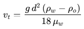
where  is gravitational acceleration (9.81 m/s²),
 is oil droplet diameter (m),
 and
 are water and oil densities (kg/m³), and
 is the dynamic viscosity of water (Pa·s)58.
Evaluating Stokes' Law across marine fuels illustrates both the quadratic penalty of small droplet sizes ( ) and the physics of OWS heating coils81:
Fluid Mixture & Temperature | Water Density ρw / Viscosity μw | Oil Density ρo / Δρ | 150 µm Rise Velocity (mm/s) | 60 µm Rise Velocity (mm/s) | 20 µm Rise Velocity (mm/s) | 5 µm Rise Velocity (mm/s) |
|---|---|---|---|---|---|---|
MDO (ISO DMA) in Fresh Water @ 15°C | 999.1 kg/m³ / 1.138 mPa·s | 840.0 / 159.1 kg/m³ | 1.7144 | 0.2743 | 0.0305 | 0.0019 |
MDO (ISO DMA) in Fresh Water @ 50°C | 988.0 kg/m³ / 0.547 mPa·s | 819.0 / 169.0 kg/m³ | 3.7886 | 0.6062 | 0.0674 | 0.0042 |
HFO (RMG 35) in Fresh Water @ 15°C | 999.1 kg/m³ / 1.138 mPa·s | 980.0 / 19.1 kg/m³ | 0.2058 | 0.0329 | 0.0037 | 0.0002 |
HFO (RMG 35) in Fresh Water @ 50°C | 988.0 kg/m³ / 0.547 mPa·s | 958.0 / 30.0 kg/m³ | 0.6725 | 0.1076 | 0.0120 | 0.0007 |
HFO (RMG 35) in Seawater @ 15°C | 1026.0 kg/m³ / 1.220 mPa·s | 980.0 / 46.0 kg/m³ | 0.4624 | 0.0740 | 0.0082 | 0.0005 |
Dividing vertical travel distance by  yields theoretical rise times72. An unheated 20 µm residual HFO droplet (980 kg/m³ at 15°C) in fresh water rises at just 0.00366 mm/s, requiring 455.5 minutes (7.6 hours) to ascend 100 mm81. Steam or electric heating coils installed in the upper or lower OWS zones attack this bottleneck in two ways: heating from 15°C to 50°C cuts water viscosity by 52% (1.138 to 0.547 mPa·s), while oil's higher thermal expansion coefficient widens Δρ from 19.1 kg/m³ to ~30.0 kg/m³21. Together, these changes triple the 20 µm HFO rise velocity to 0.01196 mm/s (reducing the 100 mm rise time to 139.4 minutes) and speed film drainage between colliding droplets72. Two caveats govern thermal operation: seawater bilge boosts Δρ over fresh-water condensate81, whereas modern VLSFO samples (such as a documented 967.4 kg/m³ case study) and high-density marine fuel grades approaching 1,000 kg/m³ at 15°C leave razor-thin density margins in fresh water83. Moreover, bilge holding tanks should not be heated during heavy ship rolling or agitation because higher temperatures reduce interfacial tension and accelerate emulsification82.
Stage 2 — Oleophilic Coalescing Plates & Matrices: Because unassisted gravity tanks realistically capture only free oil ≥150 µm72, Stage 2 channels water through closely spaced corrugated or flat inclined plates (angled at 55–60° from horizontal so solids slide into a lower hopper while oil migrates upward) or polypropylene/PTFE oleophilic ("oil-loving") mesh media14. Assuming a vertical rise distance of 6.35 mm (0.25 inches) between plates, the 50°C heated 20 µm HFO droplet reaches the upper plate surface in 8.85 minutes (531.1 s)—a combined 51.5-fold reduction relative to the unheated 100 mm open-tank path14. Droplets wetting the oleophilic surfaces coalesce into larger globules until viscous drag detaches them to float upward, capturing free and dispersed oil down to ~20 µm (10–15 µm under ideal laminar conditions)58. Separator vendor data note that standard PVC plates warp above 60°C (140°F), requiring polypropylene, FRP, or stainless steel internals in heated units58.
Stage 3 — Emulsion-Breaking & Polishing Media: Mechanical coalescers cannot break chemically stabilized emulsions (<20 µm droplets encased in surfactant films)58. Under IMO Resolution MEPC.107(49) (mandatory for installations on or after 1 January 2005), OWS units must produce ≤15 ppm effluent even when challenged with Test Fluid C—a surfactant-stabilized emulsion containing per kilogram 947.8 g fresh water, 25.0 g Test Fluid A (RMG 35 residual oil ≥980 kg/m³), 25.0 g Test Fluid B (DMA distillate ≥830 kg/m³), 0.5 g anionic surfactant (sodium dodecylbenzene sulfonate), and 1.7 g black ferrosoferric oxide (Fe₃O₄, 90% <10 µm)17. To resolve sub-20 µm emulsions and trace hydrocarbons, Stage 3 and pre-treatment systems deploy three physical-chemical mechanisms.
First, organoclays and hydrocarbon-absorbent microfibers provide high-capacity adsorption: wastewater treatment guides report that organically modified clays bind 30–50% of their weight in oil (roughly seven times the oil capacity of granular activated carbon) and are typically blended 30% organoclay with 70% anthracite coal to prevent clay swelling from blinding or rupturing housings71, while finely criss-crossed oleophilic polypropylene microfibers trap droplets below 9 µm14. Second, granular activated carbon (GAC), placed downstream of organoclay or coalescer media to avoid rapid oil fouling, strips dissolved light aromatics (<5 µm, including benzene, toluene, and xylene) and residual surfactants71. Third, chemical emulsion splitting and coagulation units—such as upstream Splitting and Filtration Units (SFUs) or chemical dosing skids—inject demulsifiers, acid pH modifiers, or coagulants (polyaluminum chloride, aluminum sulfate, ferric chloride) plus polymers to rupture surfactant films before filtration27. However, demulsifier chemistry literature cautions that overdosing can depress interfacial tension below 0.001 mN/m, creating thermodynamically stable nanoscale microemulsions (5–50 nm) that resist all mechanical separation94. While hydrophilic surface-modified membranes (such as MMT/PVP composites), reverse osmosis, Dissolved Air Flotation (DAF, <10 µm), and centrifugal OWS designs are documented across industrial and shipboard treatment systems16, exact pore-size ratings and transmembrane pressures for commercial shipboard Stage 3 ultrafiltration cartridges were not detailed in the consulted sources.
4. 15 ppm Oil Content Monitor (OCM) & 3-Way Valve Logic
Positioned on the final meter of OWS outlet piping, the 15 ppm Bilge Alarm (OCM) continuously verifies compliance prior to overboard release9. Monitors type-approved under MEPC.107(49) must measure Test Fluids A (RMG 35), B (DMA), and C (surfactant/iron-oxide emulsion) accurately without operator recalibration when bilge fuel types change28. During type approval, units are tested at 0 ppm, 15 ppm, and full scale alongside contaminant and color challenges91. Although the exact statutory tolerance number in paragraph 2.2.1 of MEPC.107(49) was omitted in the consulted extract17, compliance inspection guides and MEPC.107(49)-certified monitor specifications cite ±5 ppm accuracy (validated on commercial units up to 30 ppm, including discrimination of 100 ppm black iron oxide in 10 ppm diesel) with ±2 ppm clean-water factory calibration18.
To distinguish true oil droplets from rust particulates and turbid bilge coloration, modern OCM units pass a pressurized representative sample stream through an optical glass cell using multi-angle scattered and transmitted light detector arrays25. Microprocessor algorithms compute oil concentration across multiple hydrocarbon types from the scattered-to-absorbed light ratio32. Because oily films, scale, and bio-fouling dim the optical glass and cause upward reading drift, units incorporate manual cleaning plungers or automated fresh-water flushing and auto-clean sleeves25.
Automatic overboard shutoff relies on strict response-time thresholds and fail-safe electrical interlocks:
- Alarm Trigger (≤5 s): Upon switching from clean water to effluent exceeding 15 ppm, the OCM must activate its alarm within 5 seconds17.
- Automatic Stopping Diversion (≤20 s): The alarm immediately commands the mandatory 3-way recirculating valve (specified as an electrically driven solenoid or valve actuator in documented MEPC.107(49) assemblies; pneumatic actuation mechanics are not separately detailed in the consulted OCM specifications) and/or pump stop to close the overboard branch and divert effluent back to the Bilge Holding Tank or OWS inlet within 20 seconds total system response time6.
- Fail-Safe Interlocks: Overboard discharge is enabled only when the monitor is powered, healthy, receiving verified sample flow, and reading ≤15 ppm9. Any power loss, sensor fault, sample-line flow interruption (monitored by a dedicated flow switch), or activation of fresh-water flushing/zeroing triggers the alarm and forces the 3-way valve into recirculation18. An alarm during clean-water flushing is an intentional MEPC.107(49) anti-tamper safeguard preventing clean water from masking oily discharge25.
For regulatory verification, the OCM internal memory must continuously record date, time, alarm state, and separator operating status, retaining unalterable data onboard for at least 18 months (viewable or printable via LCD, USB, or RS-232, and preserved onboard even if the meter is replaced)16. Units must be recalibrated by the manufacturer or an authorized agent—or have the pre-calibrated measuring cell exchanged—at least every 5 years (or shorter maker interval), with a valid calibration certificate kept onboard for IOPP surveys9.
5. Failure Modes, Emulsions & Port State Control Traps
Most shipboard OWS failures trace not to separator hardware flaws, but to upstream chemical contamination, deferred valve maintenance, and documentation mismatches—each carrying major Port State Control (PSC) detention exposure6.
Chemical & Mechanical Emulsions: Ordinary soaps, galley/laundry wash water, boiler-water alkaline treatments, and non-quick-break degreasers act as surfactants that slash interfacial tension and encase <20 µm oil droplets in charged films that bypass gravity baffles and disarm oleophilic coalescers25. Aged bilge mixtures, blended waste oils, and centrifugal transfer pumps compound this into stable, milky emulsions6. Whereas optical glass fouling causes a slow upward OCM drift and trapped air bubbles cause erratic scatter spikes, an emulsion hits the OCM as an abrupt step-change jump25. Prevention relies on segregating detergent wash water, substituting quick-break degreasers (formulated to lift grease during washing and release free oil rapidly in quiet holding tanks)31, decanting surface oil before OWS runs25, tracking differential pressure to renew saturated or channeled coalescers early25, and venting/de-sludging Stage 1 routinely25.
Mechanical Valve & Piping Faults: Accident investigations highlight seized emergency bilge suction valves frozen by corrosion due to lack of regular exercising—crippling casualty dewatering when normal bilge pumps are overwhelmed—whereas crew familiarity and functional suction allowed rapid stabilization during documented machinery-space flooding cases (such as MAIB Report No. 14/2019 and cases reviewed in the EMSA Annual Review 2022)1. Similarly, SDNR valves jammed open by rust scale allow cross-compartment flooding or seawater backflow, while SDNRs seized shut block well drainage5. Worn mud box gaskets admit air that breaks suction and risks rapid elastomer stator burnout in progressive cavity feed pumps5.
Port State Control Traps: Under Paris MoU, Tokyo MoU, and USCG regimes, absent, deteriorated, or inoperable OWS filtering units, failed 15 ppm alarms, or insufficient sludge/holding tank capacity are explicit grounds for detention18. Industry summaries of the Paris MoU 2025 Annual Report record 16,474 inspections, 688 detentions (a 4.18% detention rate, up from 4.03% in 2024), and 19 bans overall110. While commercial compliance providers estimate that 32% of detentions involve oil compliance violations (costing 48–96 hours and $85,000–$180,000 per incident105) and a Panama Canal service guide attributes 40% of MARPOL detentions to mismatched coordinates or tank soundings38, these specific breakdown shares derive from vendor guides rather than official IMO statistical series. A loss-prevention briefing citing a 2014 US Department of Justice report further notes that OCMs were intentionally "tricked" (e.g., via closed sample valves or continuous flush water) in roughly one-third of prosecuted bypass cases16.
PSC Inspection Focus | Statutory / Technical Criterion | Common Trap or Failure Mode |
|---|---|---|
15 ppm & Flow-Loss Trip Test | Alarm activates in ≤5 s; 3-way valve diverts in ≤20 s on >15 ppm oil, power loss, or sample-flow loss18. | Sample valve throttled/shut, fresh-water flush left open, or slow/stuck 3-way actuator6. |
OCM Calibration & Accuracy | Valid calibration certificate (≤5-year interval / IOPP renewal); ±5 ppm accuracy benchmark9. | Expired certificate or drifted optical cell reading <15 ppm on >15 ppm sample18. |
18-Month OCM Log vs. ORB Part I | Unedited 18-month digital log matches ORB Part I (kept 3 years), soundings, and en-route/Special Area positions8. | Unexplained log gaps, anchor/Special Area discharge timestamps, or retrospective uniform-ink ORB entries18. |
Piping, Locks & Spares | Overboard valve shut with numbered seal logged under ORB Code I; Reg. 13 shore flange (215 mm OD, 6 bolts) fully bolted; spare filter onboard8. | Unlogged broken seals, missing flange bolts, oil film in clean-side discharge pipes, or portable "magic pipe" hoses7. |
Beyond administrative detentions, knowing MARPOL or Oil Record Book falsification in jurisdictions such as the United States constitutes a felony under the Act to Prevent Pollution from Ships (APPS), exposing companies and officers to criminal prosecution while permitting courts to award up to half of imposed fines to whistleblowers8. Even without deliberate bypasses, persistent nuisance alarms from detergent-contaminated bilges or fouled optical cells have historically prompted crews to disable alarms or take OWS/"White Box" units offline46, underscoring that disciplined bilge segregation, quick-break cleaners, scheduled coalescer renewal, and verified 18-month log reconciliation are indispensable to safe and compliant operations18.
References
- Emergency Bilge Suction Explained: SOLAS Requirements and, https://maritimeducation.com/emergency-bilge-suction-explained-solas-requirements-and-operation/
- Bilge Pumping Systems Survey Guidelines | PDF - Scribd, https://www.scribd.com/document/980750667/Instruction-on-Bilge
- Bilge system - Marine Engineering, https://marineengineering.softecks.in/622/
- SOLAS Bilge Pumping System Requirements | PDF | Ships - Scribd, https://www.scribd.com/document/270572022/Bilge-Pump-SOLAS-Regulations-for-Merchant-Ships
- Ship Bilge System Maintenance & Inspection Guide, https://marineinspection.app/blog/ship-bilge-system-maintenance-inspection-guide
- OWS 15 ppm Alarm: Causes and Onboard Troubleshooting - OCEUM, https://oceum.com.br/ows-15-ppm-alarm-troubleshooting/
- EMM-1: Environmental Management Guide | PDF | Pollution - Scribd, https://www.scribd.com/document/819763382/Emm
- MARPOL Annex I engine room rules (regulations 12 to 17), https://alsafwanmarine.com/academy/environmental-compliance/marpol-annex-i-engine-room
- What Is a 15ppm Bilge Alarm and When Is It Required? - Rivertrace, https://rivertrace.com/what-is-a-15ppm-bilge-alarm/
- Bilge Pump vs Bilge Ejector: Which Does Your Ship Need?, https://ctp-pumps.com/bilge-pump-vs-bilge-ejector/
- MSC.1/Circ.1424 - Netherlands Regulatory Framework (NeRF), https://puc.overheid.nl/doc/PUC_2347_14?exp=2
- Bilge and Ballast Systems - Elegant Manual - Coast Guard, https://www.dco.uscg.mil/Portals/9/MSC/PRG/PRG.E1-02.2020.07.10.Bilge_and_Ballast_Systems.pdf
- Annex I - Unified Interpretations - MARPOL Training Institute, https://www.marpoltraininginstitute.com/MMSKOREAN/MARPOL/Annex_I/ui1.htm
- Oil Water Separators-101 - RGF Environmental Group, https://rgf.com/article/oil-water-separators/
- Regulation 15 - Control of discharge of oil - MARPOL Training Institute, https://www.marpoltraininginstitute.com/MMSKOREAN/MARPOL/Annex_I/r15.htm
- Bilge Water Management & Pollution | PDF | Ships - Scribd, https://www.scribd.com/document/455566180/Bilge-Water-Management-LP-Briefing
- MEPC.107(49) - Revised Guidelines and Specifications for Pollution, https://media.liscr.com/marketing/liscr/media/liscr/online%20library/maritime/mepc%20resolution%20107_49,%20as%20amended.pdf
- bilge-oil-oily-water-separator-inspections-marine-compliance, https://marineinspection.app/blog/bilge-oil-oily-water-separator-inspections-marine-compliance
- RESOLUTION MEPC.266(68) (adopted on 15 May 2015, https://wwwcdn.imo.org/localresources/en/KnowledgeCentre/IndexofIMOResolutions/MEPCDocuments/MEPC.266(68).pdf
- Implementation of Amendments to Regulation 12 of MARPOL Annex, https://www.irclass.org/technical-circulars/implementation-of-amendments-to-regulation-12-of-marpol-annex-1-resolution-mepc266-68/
- Oily Water Separator Operation Guide | PDF | Gases | Soft Matter, https://www.scribd.com/document/67836235/06-Ows-Sweage
- SOLAS Ch. II-1 Reg. 35-1 - Bilge pumping arrangements | IMORULES, https://www.imorules.com/GUID-71A0C980-55E4-4BB0-8C88-859BADC26EC4.html
- Cargo Hold Bilge Inspection Guide | PDF | Pump | Valve - Scribd, https://www.scribd.com/presentation/730885720/Cargo-Holds-Inspection
- Ship Eductors / Ejectors Explained: Types & Operational Uses, https://www.marinepublic.com/blogs/training/781159-ship-eductors-ejectors-explained-types-operational-uses
- Oily Water Separator 15ppm Alarm Troubleshooting Guide, https://marineinspection.app/blog/oily-water-separator-15ppm-alarm-troubleshooting-guide
- rivertrace - smart bilge - 15 ppm oil content monitor, https://www.smtssg.com/15-ppm-bilge-alarms-oil-content-monitor/
- Bilge Water Treatment, https://www.rwo.de/wp-content/uploads/2021/07/rwo-bilge-water-treatment.pdf
- Smart Bilge - 15 ppm oil content monitor - Rivertrace - Insatech Marine, https://www.insatechmarine.com/products/emission-discharge/bilge-wash-water/rivertrace-smart-bilge/
- Why the right oily water pump makes all the difference - Ultraspin, https://www.ultraspin.co.za/oily-water-pump/
- Cargo Hold Preparation Tips for Bulk Carrier Officers - Marine Public, https://www.marinepublic.com/blogs/merchant-fleet/700029-cargo-hold-preparation-tips-for-bulk-carrier-officers
- 20 Important Factors For Oily Water Separator Operation On Ships, https://www.marineinsight.com/20-important-factors-for-oily-water-separator-operation-on-ships/
- Rivertrace Engineering (RTE) SMART Bilge 15PPM Oil Content, https://louissafety.com/rivertrace-engineering-rte-smart-bilge-15ppm-oil-content-monitor/
- Oily Water Separator PSC Inspection Guide | PDF - Scribd, https://www.scribd.com/document/979692365/4-OWS-for-PSC-Inspection
- Oily Water Separators – Hints and Tips - Dromon Bureau of Shipping, https://www.dromon.com/2023/07/25/oily-water-separators-hints-and-tips/
- UI SC251 “Controls of emergency bilge suction valve in periodically, https://www.ccs.org.cn/ccswz/file/download?fileid=201900004000002196
- RESOLUTION MEPC.314(74) (adopted on 17 May 2019), https://wwwcdn.imo.org/localresources/en/KnowledgeCentre/IndexofIMOResolutions/MEPCDocuments/MEPC.314(74).pdf
- Rivertrace SMART BILGE 15ppm Oil Content Monitor, https://smtsmarine.com/rivertrace-smart-bilge-15ppm-oil-content-monitor-advanced-marine-bilge-monitoring/
- Oily Water Separator Compliance - Panama Ship Service, https://panamashipservice.com/oily-water-separator-compliance-a-comprehensive-guide-for-panama-canal-transits-2026/
- Revised MARPOL requirements for oil residue (sludge) piping, https://www.dromon.com/2016/09/16/revised-marpol-requirements-for-oil-residue-sludge-piping-arrangements/
- Uniform Application of MARPOL Annex I, Revised Regulation 12, https://iacs.s3.af-south-1.amazonaws.com/wp-content/uploads/2022/05/24124701/rec-121-rev1-corr1-june-2021-ul.pdf
- The conditions that open a machinery space oily mixture discharge, https://bellbook.net/en/blog/oily-water-discharge-conditions-annex-i-15
- Whitebox - discharge monitoring unit - Marinfloc, https://www.marinfloc.com/products/discharge-monitoring-units/whitebox
- Cruise Ship Discharge Assessment Report, - epa nepis, https://nepis.epa.gov/Exe/ZyPURL.cgi?Dockey=P1002SVS.TXT
- Aarnio M. Cruise Ship Handbook 2023 | PDF - Scribd, https://www.scribd.com/document/1025204508/Aarnio-M-Cruise-Ship-Handbook-2023
- There is no such thing as a tamper-proof system, https://www.rivieramm.com/news-content-hub/news-content-hub/there-is-no-such-thing-as-a-tamper-proof-system-42217
- Court Monitor Report: Princess Cruises | PDF - Scribd, https://www.scribd.com/document/411156722/UNITED-STATES-DISTRICT-COURT-SOUTHERN-DISTRICT-OF-FLORIDA-FIRST-ANNUAL-REPORT-OF-THE-COURT-APPOINTED-MONITOR-2017-2018
- Pumps and pumping systems in Engine Room | Knowledge Of Sea, https://knowledgeofsea.com/pumps-and-pumping-systems-in-engine-room/
- Regulation 11 - Bilge pumping arrangements, https://www.imorules.com/GUID-E43AF84E-E6DD-4F5D-BA74-38DE065981A5.html
- Part 6: bilge pumping arrangements - GOV.UK, https://assets.publishing.service.gov.uk/media/5a7c7c42ed915d48c24100da/con1_2a2pt6.pdf
- PROPOSED DESIGN CRITERIA FOR A BILGE PUMPING SYSTEM, https://www.intmaritimeengineering.org/index.php/ijme/article/download/758/18
- Section 7 Piping systems and their fittings - imorules, https://www.imorules.com/LRSHIP_PT5_CH13_7.html
- Marine & Shipbuilding Valve Solutions: A Comprehensive Guide, https://www.delcovalves.com/solution/marine-shipbuilding/
- CARGO HOLD BILGE WELLS - IMCS Training Academy, https://imcs-training.eu/wp-content/uploads/sites/2/2019/10/Minimanual-Bilge-strum-box.pdf
- Understanding SDNR (Screw-Down Non-Return) Valves, https://bronzevalve.co.uk/understanding-sdnr-valves/
- Bulk Carrier Cargo Bay Drainage Systems, https://www.qh-shipping.com/Bulk-Carrier-Cargo-Bay-Drainage-Systems-id68894907.html
- Monitoring hold bilges during loaded passage of a bulk carrier, https://bulkcarrierguide.com/bilge-monitoring.html
- SOLAS II-1/35-1 Bilge Pumping Update | PDF | Shipping - Scribd, https://www.scribd.com/document/666285443/MSN-09-2010-Amendment-to-International-Convention-on-Safety-of-Life-at-Sea-2010
- Coalescing Plate Separator Systems: Engineering Design Guide, https://wxwatertech.com/coalescing-plate-separator/
- When to Use Progressive Cavity Pumps - Liberty Process, https://www.libertyprocess.com/when-to-use-progressive-cavity-pumps.html
- Oily Water Pump Selection: VS4 vs Progressive Cavity vs Gear, https://industrialmonitordirect.com/blogs/knowledgebase/oily-water-pump-selection-vs4-vs-progressive-cavity-vs-gear
- Progressive Cavity vs Centrifugal Pumps: Which Wins? | NOVA, https://novapservices.com/progressive-cavity-vs-centrifugal-pumps/
- A Comprehensive Guide to Progressive Cavity Pump, https://www.globalpumps.com/blog/progressive-cavity-pump-guide
- When and Why to Choose Progressive Cavity Pumps for Viscous, https://roperpumps.com/when-and-why-to-choose-progressive-cavity-pumps-for-viscous-abrasive-fluids/
- Understanding Progressing Cavity Pumps - SPS Wiki, https://www.sps-pumps.com/wiki-for-industrial-pumps/progressive-cavity-pumps/
- How to Maintain a Progressive Cavity Pump - Channel Pumps, https://channelpumps.com/guides/how-to-maintain-a-progressive-cavity-pump
- How to Prevent Dry Running Damage in Progressive Cavity (PC, https://www.hnpapu.com/info-detail/how-to-prevent-dry-running-damage-in-progressive-cavity-pc-pump-stators
- Can a Progressive Cavity Pump Run Dry? - Thermac, https://thermacgroup.com/resources/can-a-progressive-cavity-pump-run-dry/
- Progressive Cavity Pump Failure: Root Causes and How to Prevent, https://www.kinetiflo.com/resources/progressive-cavity-pump-failure-root-causes-and-how-to-prevent/
- Progressive Cavity Pump PCP Elastomer and Failure Modes, https://ifactoryapp.com/industries/oil-and-gas/progressive-cavity-pump-pcp-elastomer-monitoring
- Centrifugal Pump vs Screw Pump: Which Pump Is Right for Your, https://vartakpump.com/blog/centrifugal-pump-vs-screw-pump/
- Emulsified Oil Organoclays Emulsified Oil Organoclays, https://img.wwdmag.com/files/base/ebm/wwdmag/document/2022/06/1655271484847-organoclays_7_01.pdf
- OIL-WATER SEPARATION AND THE IMCO PERFORMANCE TEST, https://library.imarest.org/record/2120/files/2147.pdf
- Section 6 Pumps on bilge service and their connections, https://www.imorules.com/LRSHIP_PT5_CH13_6.html
- Eductor Pump on Ship - Working Principles & How to Operate, https://planm8.io/blog/eductor-pump-on-ship
- Ballast Eductor | Bilge Eductor - Boosting Ship Performance, https://www.crystaltcs.com/ballast-eductor.php
- Vita Motivator Marine Eductors — Bilge, Ballast & Cargo, https://jet-pump.com/vita-motivator/
- Maintenance of marine eductor - Marine Pump Works, https://www.marinepumpworks.com/media/maintenance-of-marine-eductor/
- Eductors for Pumping, Lifting Liquids & Handling Slurries or Solids, https://www.venturipumps.com/eductor.html
- Progressive Cavity Pumps: How They Work and Alternatives, https://eddypump.com/education/progressive-cavity-pumps/
- The API 421 Standard Explained - Oil Water Separators | Mercer, https://oil-water-separators.com/when-why-we-started/the-technical-implications-of-api-421/
- unknown_url
- What Factors Affect Separation in Oily Water Separator on Ships?, https://www.marineinsight.com/what-factors-affect-separation-in-oily-water-separator-on-ships/
- The Alfa Laval Adaptive Fuel Line Blue Book, https://assets.alfalaval.com/documents/peb78ef62/alfa-laval-adaptive-fuel-line-blue-book-2026-edition-application-brochure-web-en.pdf
- VLSFO's - the concerning fuel management issues so far, https://www.vpsveritas.com/knowledgecentre/articles/vlsfos-concerning-fuel-management-issues-so-far
- Achieving API 421 Oil Water Separator Compliance: Effectiveness, https://ecologixsystems.com/articles/api-421-compliance-effectiveness-and-upgrades
- Coalescing Plate Oil Water Separator - Baldwin Industrial Systems, https://www.baldwin.com.au/wastewater-treatment-products/coalescing-plate-oil-water-separator/
- Oil/Water Separator Theory of Operation - Hydroflotech, https://hydroflotech.com/oil-water-separator-theory-of-operation/
- Oil Water Separator Guide | Oil Spill Products Limited, https://oilspillproducts.co.uk/blogs/news/oil-water-separator-guide-oil-spill-products-limited
- 7 Oil-Water Separation Methods Used in Industry - Rodanco, https://rodanco.nl/oil-water-separation-methods/
- Using organoclays to remove oil from water, https://www.wateronline.com/doc/using-organoclays-to-remove-oil-from-water-0003
- Res.MEPC.107(49) - Revised guidelines and specifications for, https://puc.overheid.nl/nsi/doc/PUC_2589_14/1/
- Oily Bilgewater Separators - epa nepis, https://nepis.epa.gov/Exe/ZyPURL.cgi?Dockey=P100DCO8.TXT
- Organoclay for Emulsified Oil Removal | PDF | Emulsion | Wastewater, https://www.scribd.com/document/465262054/Removing-Emulsified-Oils-from-Wastewater
- How Do You Break an Emulsion for Oil-Water Separation? - Rodanco, https://rodanco.nl/how-to-break-an-emulsion/
- Beyond Low Interfacial Tension—The Science of Rational Emulsion, https://www.unpchemicals.com/news/demulsifiers-beyond-low-interfacial-tensionthe-science-of-rational-emulsion-breaking.html
- Oil/Water Mixtures and Emulsions Separation Methods—An Overview, https://pmc.ncbi.nlm.nih.gov/articles/PMC10053512/
- SMART Bilge+ monitor – 15ppm bilge alarm - Rivertrace, https://rivertrace.com/products/smart-bilge-15ppm-oil-content-monitor/
- Rivertrace Smart Bilge Monitor - 15 PPM Bilge Alarm, https://separatorequipment.com/products/oily-water-separator/rivertrace-smart-cell/
- Brannstrom BilgMon 488 15 PPM Bilge Alarm - Advanced Oil, https://www.smtssg.com/brannstrom-bilgmon-488-15-ppm-bilge-alarm-advanced-oil-content-monitoring-for-marine-protection/
- Deckma OMD‑24 Oil Content Meter with 15 ppm alarm, ensuring, https://petriknaval.eu/archives/6598
- 15 PPM Bilge Alarm Monitors, OWS, Compliance, And Calibration, https://www.shivtech.com/post/15-ppm-bilge-alarm-monitors-ows-compliance-and-calibration-best-practices-2026-edition
- RightShip Inspection Ship Questionnaire (RISQ), https://rightship.com/hubfs/RISQ-3.2.pdf
- Ensuring Compliant Bilge Water Discharge for Vessels, https://www.deyuanmarine.com/Oily-Water-Separators-Ensuring-Compliant-Bilge-Water-Discharge-for-Vessels-id08855245.html
- Rivertrace SMART Bilge 15ppm Alarm - Maritronics, https://maritronics.com/product/smart-bilge-monitor-15ppm-bilge-alarm
- Marine Oil Compliance Failures Causing Vessel Detentions, https://marineinspection.app/blog/marine-oil-compliance-failures-vessel-detentions
- How Oil-Water Separators Work and How to Use Them, https://www.oilandwaterseparator.com/wp-content/uploads/2014/09/How-Oil-Water-Separators-Work-and-How-to-Use-Them-Paper.pdf
- Quick Break Degreasers | Safe Heavy Duty Degreaser - Envirofluid, https://envirofluid.com/quick-break-degreasers-safe-eco-friendly-heavy-duty-degreaser-technology/
- PSCC59/2026/03 Detention and Action Taken - Paris MoU, https://parismou.org/download/pscc59-2026-03-guidelines-on-detention-and-action-taken/
- COMDTINST M16000.73, Port State Control, 20Sep2021, https://www.dco.uscg.mil/Portals/9/OCSNCOE/References/COMDTINSTs/CI-16000.73-PSC.PDF?ver=piR_bu_57BnywZZyuXzT0A%3D%3D
- Port State Control Inspection Guide: Process and Preparation, https://synergeticshippingsolutions.com/resources/port-state-control-inspection-guide/