Part 1: System cardDel 1: Systemkort
1. Core Function
A ship’s power plant generates AC electricity using auxiliary diesel alternators and shaft generators, synchronizing voltage, frequency, and phase angle on the Main Switchboard (MSB) for parallel operation1. Step-down transformers and fault-tolerant insulated or high-resistance earthed networks distribute power across high-load machinery and vital navigation, safety, and hotel consumers6. Overload relays protect bus stability via preferential tripping, while uninterruptible power supplies and an autonomous Emergency Generator feeding the Emergency Switchboard deliver automatic backup during blackouts9.
2. Primary Operational Tasks
- Continuous Electrical Generation: Maintains uninterrupted shipboard power via at least two auxiliary diesel generator sets, supplemented during sea passages by main-engine Power Take-Off (PTO) shaft generators for lower specific fuel consumption2.
- Parallel Load Sharing: Synchronizes incoming alternators onto the live busbar and balances active power (kW) through governor speed droop and reactive power (kVAR) through AVR quadrature droop3.
- Multi-Tier Voltage Transformation: Steps down medium/high-voltage AC (1–15 kV under IEC 60092-503) via Dyn11 transformers to low-voltage 0.6/1 kV distribution (documented examples span 415–480 V three-phase and 120–240 V single-phase, alongside conventional 6.6 kV/440 V/230 V shipboard tiers not explicitly itemized in available standards excerpts) plus 24 V DC battery banks and UPS systems8.
- Preferential Tripping: Automatically disconnects non-essential loads in staged intervals—typically 5, 10, and 15 s in marine practice—during generator overload to prevent main breaker disconnection10.
- Automatic Blackout Recovery: Disconnects the Emergency Switchboard (ESB) interconnector on main power failure, auto-starts and connects the Emergency Generator within 45 seconds, maintains continuous DC/transitional power, and supports dead-ship propulsion restoration within 30 minutes1.
3. System Interconnections
- Inputs: Auxiliary diesel engines draw heavy fuel oil (HFO) or marine diesel/gas oil (MDO/MGO; emergency units require flashpoints ≥43°C), compressed starting air (typically 20–30 bar per marine consultancy guidance), lubricating oil, and cooling water1; shaft generators capture mechanical torque from the main engine crankshaft or intermediate propeller shaft2; shore-power inlets accept flexible shore cables with phase-sequence switching10; and instrumentation monitors busbar voltage, frequency, phase angle, line currents (droop and reverse-power CTs), and continuous earth-fault/insulation resistance3.
- Outputs: Main feeders supply propulsion/DP control interfaces and Power Take-In (PTI) shaft boost12, engine-room auxiliaries (fuel, lube oil, cooling water pumps, air compressors), steering gear, galleys, and hotel services1 (note: specific thruster, cargo pump, ballast pump, and HVAC consumer feeders are not explicitly detailed in the reviewed technical sources, though general high-load power distribution is covered9); an interconnector feeder supplies the ESB9; battery chargers and UPS units feed GMDSS, BMS/AMS automation, and transitional banks12; and alarm circuits drive Engine Control Room (ECR), MSB/MCR battery-discharge, and Unattended Machinery Space (UMS) bridge alerts22.
4. Redundancy & Criticality
Under SOLAS Chapter II-1, main electrical plants require at least two generating sets capable of supplying all normal operational and habitable services without emergency power13. Regulations 42 (passenger ships), 43 (cargo ships), and 44 mandate an independent emergency source installed above the uppermost continuous deck, readily accessible from the open deck, and aft of the collision bulkhead9. Marine regulatory summaries specify continuous operation at up to 22.5° list and 10° trim28, using independent ≥43°C flashpoint fuel, cold starting at 0°C via dual independent starting systems (3 primary starts plus 3 additional starts within 30 minutes), and automatic load pickup within 45 seconds9. Required endurance is 18 hours for cargo vessels and 36 hours for passenger vessels (reducible to ≥12 hours on approved short voyages)9; a May 2026 compliance blog report citing a 2025 IACS inspection campaign across 36,723 ships recorded 97.68% passing without emergency-power deficiencies (leaving 2.32% with deficiencies)29.
Part 2: Technical deep diveDel 2: Teknisk dybdeanalyse
1. Auxiliary Generators & Shaft Generators (PTO)
Shipboard base-load electricity is primarily generated by auxiliary diesel generator sets operating on HFO, MDO, or MGO with dedicated service tanks and rapid fuel-changeover capability13. While IACS mechanical rules (UR M78) explicitly encompass four-stroke and two-stroke engines12, detailed four-stroke thermodynamic and mechanical internals are not covered in the available technical sources, which instead emphasize prime-mover auxiliary dependencies—compressed starting air (typically 20–30 bar per marine service guidance), lubricating oil priming, fuel filtration, and cooling water circulation1. Each prime mover drives a synchronous alternator at constant synchronous speed governed by:
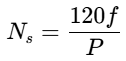
where  is rotational speed in RPM,
 is electrical frequency (50 or 60 Hz), and
 is the number of alternator magnetic poles3. Marine alternators adopt brushless synchronous excitation, eliminating carbon brushes and commutators in favor of a stationary exciter stator and a shaft-mounted rotating diode rectifier assembly that feeds DC field current directly to the main rotor15.
A solid-state Automatic Voltage Regulator (AVR) samples stator terminal voltage, compares it against an internal reference, and modulates exciter field current; vendor technical guides report millisecond-scale response maintaining steady-state voltage within ±1–2% across load changes15. Marine AVRs also incorporate Under-Frequency Roll-Off (UFRO or DIP)—reducing output voltage proportionally when speed drops below a 47.5 Hz (50 Hz) or 57 Hz (60 Hz) knee point (e.g., 1–3% voltage drop per 1% frequency dip on Stamford MX322 units) so diesel engines can recover speed under sudden heavy loads16—together with over-voltage tripping, delayed field-forcing current limits, and quadrature droop for parallel reactive sharing15. How the AVR itself is powered dictates fault sustainment and harmonic tolerance:
Excitation System | AVR Power Source | Short-Circuit & Transient Capability | Operational Strengths | Trade-Offs & Limitations |
|---|---|---|---|---|
Shunt (Self-Excited) | Main stator output terminals36 | ~100% rated short-circuit current per distributor guide; excitation collapses on terminal voltage dip35 | Simple, compact, low capital cost; suited for small (<250 kVA) linear loads36 | Vulnerable to waveform distortion and non-linear loads; lacks sustained fault current without booster CTs36 |
AREP / AREP+ | Two stator auxiliary windings (H1 voltage + H3 current booster); AREP+ adds exciter pole permanent magnet inserts36 | Up to 300% short-circuit current for 10 s (Leroy-Somer LSA rating); AREP+ adds up to 30% starting kVA36 | Supports heavy motor starts and downstream fault clearing within standard frame lengths36 | Auxiliary windings remain inside the main stator rather than fully isolated36 |
Permanent Magnet Generator (PMG) | Separate shaft-mounted PMG on non-drive end16 | Up to 300% short-circuit current for 10 s (LSA); vendor blog cites ~250 ms recovery on 60% load step36 | Electrically isolated from terminal harmonics; preserves black-start remanence; recommended for island mode35 | Increases axial generator length, cost, and part count, which Caterpillar notes can lower statistical reliability37 |
During steady sea passages, vessels improve overall plant economy and compliance with EEDI, EEXI, and CII targets by driving a Power Take-Off (PTO) shaft generator off the low-speed two-stroke main engine (ME), exploiting its superior specific fuel oil consumption while cutting auxiliary engine hours and maintenance2. Shaft generators mount via ME front-end crankshaft gears (FED/FTD with torsional dampers, toothed/elastic couplings, and multi-disk clutches), aft-end tunnel gears (ATG) on the propeller shaft, or shaft-inline stators/rotors mounted directly on intermediate shaft flanges or retrofit tensioning yokes without added bearings2. Hybrid PTO/PTI plants can also reverse power flow into Power Take-In (PTI / Boost) mode—assisting propulsion from auxiliary gensets—or Power Take-Home emergency propulsion14.
Because Fixed-Pitch Propellers (FPPs) and Controllable-Pitch Propellers (CPPs) following optimal combinator curves vary shaft RPM with ship speed, maintaining a stable 50 or 60 Hz bus requires either mechanical speed regulation or static power-electronic conversion:
PTO Stabilization Architecture | Operating Mechanism | Parallel & Propulsion Flexibility | Efficiency & Engineering Trade-Offs |
|---|---|---|---|
Constant-Speed CPP + Step-Up Gear (e.g., RENK GCR) | Maintains constant ME speed through step-up gear while thrust varies via propeller pitch2 | Eliminates converters, but restricts PTO to fixed shaft RPM14 | Running constant RPM at reduced ship load lowers propeller efficiency compared with combinator pitch curves14 |
Mechanical Constant Speed Drive (CSD) (e.g., RENK RCF) | Differential epicyclic gear with hydrostatic superposition drive trims speed to hold constant frequency across varying ME RPM2 | Allows converter-free fixed-frequency PTO even on FPP vessels2 | RENK promotional material claims up to 15% efficiency gains over gensets and <10 man-hours/year maintenance; notably, MAN Energy Solutions PTO documentation omits mechanical CSD gears2 |
Thyristor Converter + Synchronous Condenser | Legacy static converter decouples variable shaft frequency; synchronous condenser supplies commutation/kVAR14 | Extends PTO speed window and enables parallel genset operation14 | Demands substantial deck space for static converter cubicles and separate synchronous condenser seating14 |
PWM / DC-Link Static Frequency Converter (EESG or PMSG) | Rectifier, DC-link, and PWM inverter synthesize fixed 50/60 Hz across wide or zero-to-max shaft RPM14 | Eliminates synchronous condenser; supports CPP combinator curves, FPP slow-steaming PTO, PTI boost, and parallel genset sharing14 | Trade press cites ≥96% machine and ~90% system efficiency for SMDERI units and EESG excitation-cutoff fault isolation26; explicit AFE/IGBT topologies and harmonic-filter designs are omitted in reviewed OEM docs14 |
2. Main Switchboard (MSB), Synchronization & Protection
To prevent a single switchboard bus fault from crippling propulsion and auxiliaries, regulatory summaries note that main busbars on plants exceeding 3 MW total installed capacity must be subdivided into at least two sections joined by removable links30. Each generator requires a dedicated control cubicle separated from adjacent cubicles by flame-retardant partitions, and shore-power connections via flexible cables require phase-sequence changeover switching unless exempt by onboard electrician procedures or non-interchangeable appliance connectors10. Main generator and feeder switching relies on Air Circuit Breakers (ACBs) (miniature circuit breakers are restricted under NEK 410 / IEC 60092-202 guidance to capacities below 35 kVA), and protection relays must allow generator ACB reconnection within 30 seconds of a trip provided bus voltage sits within 85–110% of rated value10. (Internal ACB arc-chute/spring-charging mechanics and proprietary auto-synchronizer controller algorithms are not detailed in the available technical documentation.)
Parallel connection of an incoming alternator—manually via synchroscope/synchronizing lamps or automatically—requires matching four conditions: identical phase sequence (R-Y-B), equal voltage magnitude, matching frequency, and zero phase-angle displacement3. Marine chief-engineer guides cite permissible synchronization tolerances of ±5% on terminal voltage (tighter industrial commissioning practice targets ±0.5 V on 120 V AVR sensing circuits to suppress circulating currents) and an oncoming frequency 0.1–0.5 Hz above the busbar (commonly 0.2–0.3 Hz when paralleling onto load, or nearly stationary at no-load)3. On a manual synchroscope, slow clockwise pointer rotation confirms the incoming machine is marginally fast so it picks up minor positive kW load upon closure; operators close the ACB slightly ahead of the 12 o'clock mark (around 11 o'clock) to compensate for breaker mechanical closing time3. Closing appreciably out of phase induces destructive pole-slipping torque capable of shearing couplings or damaging engine crankshafts42.
Once paralleled, active power (kW) and reactive power (kVAR) are governed independently. Active kW sharing relies on prime-mover governor speed droop—typically set to 3–4% so machines share load proportionally without fighting; running multiple sets in isochronous mode triggers governor hunting and reverse-power trips17. Reactive kVAR sharing relies on AVR quadrature droop fed by a phase droop current transformer (typically 5–8% droop, such as 0.22 A CT input for 5% droop at zero PF on Stamford MX322 units or 8% at 0.8 PF on Leroy-Somer R180 units)16. An over-excited machine with higher terminal voltage exports kVAR to the bus, whereas an under-excited machine absorbs kVAR, driving circulating cross-currents that heat stator windings and distort power factor17.
Two core protective schemes defend the MSB against prime-mover failure and sustained overload. First, directional wattmetric reverse-power relays (ANSI 32) trip the generator ACB if prime-mover torque drops—due to fuel loss, governor fault, or loss of excitation—and the busbar begins motoring the alternator11. Relay vendor and IEC 60092-202 specifications place pickup sensitivity at 2–15% (-5% to -15% rated power, routinely tested by governor offloading to ~10%) with a 3–10 second (typically 5–10 s) time delay to ride through transient paralleling swings; miswired CT polarity is a common commissioning error that causes immediate reverse-power trips at no load10. Second, IEC 60092-201 and 202-compliant preferential tripping sheds non-essential services (such as galley and accommodation feeders) automatically during overload before main generator ACBs trip10. Engineering practice conventionally stages preferential shedding at 5, 10, and 15 seconds (historically using timed dashpot relays), complementing UMS standby generator auto-start set around 80–85% bus load11; if overload persists past the final shed stage, a blackout occurs11.
3. Marine Distribution Architecture & Earth Faults
To maintain vital propulsion, steering, and safety services through a single insulation failure, SOLAS Ch. II-1 Reg. 45.4.3, IEC 60092-502/503, and IEC 61892-2 favor insulated neutral (IT) or high-resistance earthed (HRG / impedance-earthed IT) networks rather than solidly earthed land grids6. In a solidly earthed TN system (IEC 60092-352 Category A), any single phase-to-hull fault triggers an immediate protective trip—and parallel TN generators require checks against harmonic equalizing currents10. Conversely, in IT and HRG Category B systems, lacking a low-impedance return path limits single earth-fault currents so breakers do not trip on the first fault, permitting continued operation (capped at 125 fault hours per year under Category B cable ratings) while crew locate and clear the defect6. If a second earth fault occurs on another phase before repair, however, the resulting double earth fault creates a phase-to-phase short circuit through the hull that phase overcurrent protection must clear immediately6.
Neutral Earthing Method | Grounding Arrangement & Sizing | Single Earth-Fault Current | Operational Continuity & Monitoring | Engineering Trade-Offs |
|---|---|---|---|---|
Isolated / Insulated Neutral (IT) | No intentional earth connection; coupled only via cable and RFI suppression capacitance6 | Very small capacitive charging current6 | Single fault causes no trip; continuous Insulation Monitoring Device (IMD) mandatory6 | Standard on LV networks; lacks resistive damping and complicates fault-branch localization |
High-Resistance Earthed (HRG) | Neutral earthed via resistor R ≤ X_C / 3 per IEC 60092-50319, ensuring resistive current exceeds total capacitive fault current6 | ≤5 A per IRS Sept 2024 guidelines (20 A/unit guidance ≤15 kV when exact data is unavailable)6 | Single fault causes no trip; requires continuous IMD/NGRM and earth ammeter or voltmeter6 | Preferred for MV networks up to 15 kV; prevents generator magnetic-core damage while aiding fault tracing6 |
Low-Resistance Earthed | Neutral earthed through lower-ohmic resistor19 | Limited to 20–100% of largest generator rated current per IEC 60092-50319 | Requires automatic fault clearance; no sustained first-fault ride-through19 | Limits fault energy relative to TN grids, but sacrifices continuous supply on first earth fault |
Solidly Earthed (TN) | Neutral solidly tied to hull/earth conductor10 | High bolted line-to-earth fault current | Immediate trip on first fault (Category A)44 | Parallel generators require harmonic circulating-current checks; drops vital circuits on first earth fault10 |
September 2024 Indian Register of Shipping (IRS) earthing guidelines conclude that peak transient overvoltages are relatively insensitive to the choice among isolated IT, impedance-earthed IT, and TN earthing, while noting that a detailed comparative analysis of line-to-earth voltage rise between IT and HRG networks is absent from that guidance6.
High-power shipboard grids generate and distribute at medium/high voltages from 1 kV up to 15 kV under IEC 60092-503 (using extruded marine cables rated 3.6/6 (7.2) kV through 18/30 (36) kV under IEC 60092-354), stepping down to 0.6/1 kV low-voltage networks (IEC 60092-353) via three-phase isolation transformers18. (While shipboard engineering conventionally specifies 6.6 kV / 440 V / 230 V tiers, the available standards and equipment manuals specifically document 1–15 kV MV/HV AC systems including 3.6/6 kV and 11 kV, LV systems spanning 300–530 V AVR ranges, 415–480 V three-phase, and 120–240 V single-phase, plus 24 V DC circuits8.) Marine distribution transformers overwhelmingly employ the Dyn11 vector group: Delta primary (D), Star secondary (y) with accessible neutral (n), and clock-11 phase shift7. Under the IEC anticlockwise phasor convention (HV at 12 o'clock), clock 11 denotes LV lagging HV by 330°—equivalently leading HV by 30°7 (though some generic transformer guides invert lead and lag phrasing49). The closed Delta primary blocks zero-sequence earth-fault currents between MV and LV networks, traps triplen (third-order) harmonics inside the delta loop, and carries unbalanced LV loads without neutral shift7. Multi-winding converter transformers (e.g., Dy11y11, Dy11d0) stagger secondary phase shifts for drive harmonic cancellation, while paralleling transformers demands identical vector group/clock number, tap voltage ratio, and closely matched short-circuit impedance per IEC 60076-17.
Low-voltage DC safety, control, and automation continuity relies on dedicated battery banks and Uninterruptible Power Supplies (UPS). Recognizing modern reliance on continuous electronic controls, IACS Unified Requirement E21 (Rev. 2, February 2024) expanded marine UPS requirements beyond transitional roles to continuous uninterruptible service for essential systems such as Dynamic Positioning (DP) control, Alarm and Monitoring Systems (AMS), and BMS12. Accumulator banks also support GMDSS under SOLAS Ch. IV Reg. 13 (1-hour endurance with an emergency generator, 6 hours without)30, 24 V DC alternator field flashing20, and emergency/transitional consumers while maintaining terminal voltage within ±12% of nominal without recharge9. Battery spaces must be separated from the ESB, finished with acid-resistant paint, designed against electrolyte spillage and gas accumulation, fitted with explosion-proof (Exd) lighting, and connected to discharge indicators on the MSB or MCR22. (Internal 24 V DC battery-charger rectifier circuits and double-conversion UPS power-stage topologies are not covered in the reviewed sources.)
4. Emergency Generator & Emergency Switchboard (ESB)
To isolate emergency power from machinery-space fires, flooding, or explosions, SOLAS Ch. II-1 Regulations 42 and 43 require the emergency generator, associated transformers, transitional battery, ESB, and emergency lighting switchboard to sit above the uppermost continuous deck, readily accessible from the open deck, and aft of the collision bulkhead9. On cargo ships of 100 m and above, Dutch inspectorate interpretations prohibit boundaries contiguous with Category A machinery spaces, main generating rooms, or the MSB29. The ESB must occupy the same compartment as the emergency generator unless operation is impaired, whereas accumulator batteries must be housed separately22. Marine regulatory notes further specify continuous operation up to 22.5° list and 10° trim, an independent fuel tank with closed-cup flashpoint ≥43°C, and an external quick-closing fuel valve9.
Under SOLAS Ch. II-1 Reg. 44 and MSC/Circ.736, emergency sets must cold-start at 0°C, with heating mandatory for colder operating regions32. Automatic sets must carry primary stored energy for at least 3 consecutive starts, plus a second independent energy source for 3 additional starts within 30 minutes unless manual starting is demonstrated effective33. For ships built on or after 1 October 1994, any single starting source must be protected from complete depletion by automatic cranking unless a second independent starting arrangement is fitted22. Accepted dual arrangements include two non-paralleled batteries, one electric battery plus hydraulic/spring/inertia/manual starting, or an air starter with a dedicated air receiver plus a second method (while purely manual-start sets may use cranking, inertia starters, hand-charged hydraulic accumulators, or powder cartridges)29. All starting, charging, and storage hardware must stay within the emergency generator room and serve only the emergency set; electric/hydraulic energy is maintained from the ESB, and compressed air receivers may charge from main/auxiliary air lines through a non-return valve inside the E-Gen room or via an ESB-powered emergency air compressor33.
During normal operation, the MSB feeds the ESB through an interconnector feeder (tie-breaker) protected at the MSB against overload and short circuit9. Upon loss of main bus voltage, the interconnector automatically opens at the ESB before the emergency breaker closes, preventing the emergency set from back-feeding a dead or faulted MSB, while non-emergency ESB circuits automatically trip off9. Where feedback from the ESB to the MSB is designed, the interconnector requires short-circuit protection at the ESB as well9, and inspectorate rules restrict parallel operation supplying non-emergency circuits to ~10 seconds via a time-limiting device29. Notably, a Tokyo MOU Port State Control safety bulletin warns that "simulated blackout" test switches often trip only a local sensing circuit and can pass periodic drills while failing during an actual shipwide blackout due to hidden interlock defects54.
Regulatory Criterion | Cargo Ships (SOLAS Ch. II-1 Reg. 43) | Passenger Ships (SOLAS Ch. II-1 Reg. 42) |
|---|---|---|
Minimum Runtime | 18 hours (3 h for muster, embarkation, and overside lighting; ≥12 h minimum on approved short voyages)9 | 36 hours (≥12 h minimum on approved short voyages)22 |
Auto-Start & Load Time | ≤45 seconds (eliminates separate 30-min transitional battery if capable of taking transitional load within 45 s)9 | ≤45 seconds mandatory automatic start and full rated load pickup22 |
Transitional Emergency Battery | 30 minutes within ±12% nominal voltage without recharge (required unless E/Gen picks up transitional load ≤45 s)9 | 30 minutes within ±12% nominal voltage without recharge (mandatory alongside ≤45 s E/Gen, including watertight door control/alarms and door closure)22 |
Mandatory Core Consumers | Emergency lighting (incl. post-2002 tanker pump-rooms), nav lights, VHF/MF/HF/SES radio, internal comms, fire detection/alarm, whistle/daylight lamp, nav gear (V/12, waivable <5,000 GT), one fire pump, and one steering gear motor (SOLAS II-1 Reg. 29/30)9 | All cargo consumers plus passenger alley/lift lighting, automatic sprinkler pump, emergency bilge pump/valves, power watertight doors, and sequential lift-to-deck escape22 |
An illustrative engineering time budget from a marine inspection platform splits the 45-second window into roughly 3 s for blackout detection, 8 s for cranking, 10 s for voltage/frequency stabilization, and 5 s for breaker closure, leaving a 19 s safety margin29.
5. Failure Modes & Blackout Recovery
Shipboard blackouts typically occur when an electrical, fuel, or mechanical fault on one running generator cascades before standby sets or load-shedding relays stabilize the MSB5. According to the ABS Blackout Awareness Advisory, prime electrical triggers include loss of excitation caused by failed AVRs, blown AVR fuses, loose sensing leads, or shorted/open rotating rectifier diodes—alongside terminal voltage collapse on shunt-excited sets under short circuit5. Fuel starvation and prime-mover mechanical trips represent equally common root causes: clogged fuel filters, unpurified or off-specification fuel, fouled injectors, faulty HFO-to-MGO changeovers, lube-oil pump failure, jacket cooling overheating or pressure loss, and worn cylinder/piston-ring assemblies all cause sudden engine derating or shutdown5.
Control and protection instabilities accelerate single-unit upsets into plant-wide blackouts. Operating paralleled governors in isochronous mode induces governor hunting and reverse-power tripping, while AVR voltage mismatches drive heavy reactive cross-currents and CT polarity errors falsely trip healthy machines11. Out-of-phase breaker closure risks severe mechanical shaft or coupling failure42. Finally, cascading overload ensues when large motor starting demands exceed online spinning reserve while standby auto-start (80–85% threshold) or staged preferential tripping (5, 10, and 15 s) fails to act in time—and repeated unsuccessful automatic restarts can exhaust compressed starting-air receivers, preventing any immediate recovery5.
Switchboard integrity relies on continuous Insulation Monitoring Devices (IMDs) and Neutral Grounding Resistor Monitoring (NGRM) to alert engineers to a first earth fault before a second fault forms a phase-to-phase short circuit6. Against high-energy internal switchgear faults, IEC/TR 61641:2014 specifies internal-arc testing for IEC 61439 low-voltage assemblies (HV switchgear is separately governed by IEC 62271-200 Internal Arc Classification56, whereas IEEE 1584 calculates worker incident energy in cal/cm² rather than containment47). Industrial technical guides note IEC 61641 testing spans 6.3–50 kA prospective fault currents (commonly 25 or 35 kA at 480 V for 0.5–1.0 s) across three arcing classes: personnel protection, restricted assembly damage, and limited continued operation47. Containment designs target 75–150 kPa enclosure pressure withstand using welded seams, baffle plates, arc-resistant gaskets, ≥3 mm corner radii, and directional vents away from personnel47. Active protection minimizes thermal let-through energy (I²t) via Zone Selective Interlocking (ZSI)—restricting upstream breaker intentional delays strictly to downstream faults—and arcing fault mitigation devices that interrupt rapidly, divert the arc into a bolted short-circuit link, or trip upstream breakers instantaneously57. (Specific optical light-sensor arc-flash relay architectures are not detailed in the reviewed IEC 61641 and vendor documentation.)
When recovery fails and stored starting energy is exhausted, the vessel enters a dead ship condition. ABS rules and IACS Unified Requirement M61 draw a sharp distinction: in a blackout, MSB power is lost but compressed air or battery energy remains available to restart a main generator; in a dead ship condition, main propulsion, boilers, and auxiliaries are stopped and no stored energy is assumed available for starting propulsion, main gensets, or essential auxiliaries5. Under SOLAS Ch. II-1 Reg. 26.4 and IACS UR M61 (Rev. 3, February 2024, effective for ships contracted on or after 1 July 2025 alongside UR M84 on essential compressed air availability), the vessel must restore starting energy, propulsion, and steering without external aid within 30 minutes12, following a defined sequential procedure (with illustrative stage times below drawn from marine consultancy recovery guidance1):
- Start Emergency Generator (<1–2 min): Verify automatic start or manually start the emergency generator using its autonomous stored energy—dedicated battery, hydraulic accumulator, spring starter, or approved manual method1. (Vessels without a compliant emergency generator instead use a hand-starting oil engine or hand-operated air compressor59.)
- Energize Emergency Switchboard (ESB): Confirm stable emergency generator voltage and frequency and close its breaker onto the ESB (with the MSB interconnector open) to restore emergency lighting, control circuits, and recovery machinery1.
- Charge Auxiliary Starting Air (~5–10 min): Start the ESB-powered emergency air compressor to pressurize the auxiliary generator starting-air receiver to required pressure (typically 20–30 bar)1.
- Prime and Start One Main Generator Engine (~5 min): Start the selected auxiliary engine’s lubricating-oil priming pump and emergency MGO pump (switching fuel inlets locally from HFO to MGO where applicable)24, then admit starting air to crank and stabilize the generator1.
- Energize Main Switchboard (MSB): Once the main generator reaches rated voltage and frequency, close its ACB to re-energize the MSB1.
- Restore Main Air Compressors and Vital Auxiliaries (~5–8 min): Sequentially start main air compressors to recharge main engine air receivers alongside essential fuel, lube oil, seawater cooling pumps, and steering gear1.
- Start Main Propulsion Engine (≤30 min total): Once main starting-air pressure, cooling temperatures, and lube-oil pressures reach operational limits, crank the main engine via compressed air to re-establish propulsion and steering within the statutory 30-minute limit1.
References
- Dead Ship Start Procedure: Technical Overview and Regulatory, https://bbc-smrmarine.com/dead-ship-start-procedure-technical-overview-and-regulatory-compliance-n18.html
- RENK Shaft Generator Efficiency Systems | PDF | Gear - Scribd, https://www.scribd.com/document/62305997/GCR-RCF-LowRes
- Generator Synchronization on Ships - NAVINSIDER, https://navinsider.com/generator-synchronization-on-ships/
- Preparing to synchronize a generator to the grid, https://electrical-engineering-portal.com/preparing-to-synchronize-a-generator-to-the-grid
- BLACKOUT AWARENESS AND PREVENTION ON SHIPS, https://ww2.eagle.org/content/dam/eagle/advisories-and-debriefs/blackout-awareness-advisory.pdf
- Guidelines on Earthing Systems for Ships and Offshore Structures, https://www.irclass.org/media/7467/guidelines-on-earthing-systems-for-ships-and-offshore-structures_irs-g-saf-08_sept-2024_new.pdf
- Transformer Vector Groups Explained (Dyn11) - AdepaTrade, https://adepatrade.com/transformer-vector-groups-dyn11-explained/
- Understanding Vector Group of Transformer (part 1), https://electrical-engineering-portal.com/understanding-vector-group-transformer-1
- SOLAS Ch. II-1 Reg. 43 - Emergency source of electrical power, https://www.imorules.com/GUID-7F31AD5F-EA75-4FB7-AFA1-04BCEFA9462B.html
- insulated and neutral earthing system, https://sites.google.com/site/frerfuninstudy/insulated-and-neutral-earthing-system
- All about Reverse Power Relay and Preferential Trips on Ship, https://electrotechnical-officer.com/all-about-reverse-power-relay-and-preferential-trips-on-ship-electrical-system/
- Summaries of IACS Resolutions published in 2024 - ClassNK, https://www.classnk.or.jp/hp/pdf/info_service/iacs_ur_and_ui/adop/2024AR.pdf
- SOLAS Regulations | Chapter II-1 | Part D - Electrical installations, https://www.electrotechnicalofficer.com/2016/08/solas-regulations-chapter-ii-1-part-d.html
- Shaft generators for low speed main engines, https://www.man-es.com/docs/default-source/marine/tools/5510-0003-03ppr.pdf
- Brushless Generator AVR: How It Works & Why It Matters, https://mtspowerproducts.com/brushless-generator-avr-how-it-works-why-it-matters/
- SPECIFICATION AND CONTROLS - STAMFORD | AvK, https://www.stamford-avk.com/sites/stamfordavk/files/2021-01/STAMFORD-MX322-Automatic-Voltage-Regulator.pdf
- Generator Synchronization Without Load: Reverse Power Trip Fix, https://industrialmonitordirect.com/blogs/knowledgebase/generator-synchronization-without-load-reverse-power-trip-fix
- IEC 60092 Shipboard Cable: Which Part Covers Your Cable - SORIVO, https://sorivocable.com/cable-standard-cross-reference-iec-60092-marine/
- INTERNATIONAL STANDARD IEC 60092-503, https://cdn.standards.iteh.ai/samples/8769/bfbd1c214447465297f22cea8234b992/IEC-60092-503-2007.pdf
- R180 - Leroy-Somer Electric Motors & Alternators, https://www.leroy-somer.com/documentation_pdf/5599_en.pdf
- 3.1 SOLAS Regulation II-1/26.4, Dead Ship Condition, https://www.imorules.com/GUID-1591094A-EA70-415C-85E4-06D0FC8B6E86.html
- SOLAS Ch. II-1 Reg. 42 - Emergency source of electrical power, https://www.imorules.com/GUID-C048F800-5412-40B3-ACCD-C562D4E4F719.html
- 4 SOLAS Regulation II-1/26 – General, https://www.imorules.com/GUID-4A0E26F6-6E0B-405F-AF05-1C19165B5C72.html
- dead ship recovery procedure, https://data.ntsb.gov/Docket/Document/docBLOB?ID=18947021&FileExtension=pdf&FileName=Dali%20-%20Dead%20Ship%20Recovery%20Procedure-Rel.pdf
- Wide range of shaft generators - RENK, https://www.renk.com/en/products/marine/shaft-generators
- The 2 Main Shaft Generator Technologies Available Now | Ship Nerd, https://shipnerdnews.com/the-2-main-shaft-generator-technologies-available-now/
- Maritime systems - bender-de.com, https://www.bender.de/fileadmin/content/Products/b/e/Maritime-Systems_B_en.pdf
- SOLAS Emergency Generator Requirements | PDF - Scribd, https://ru.scribd.com/document/598733782/1
- SOLAS Emergency Generator Inspection & Black-Start Test, https://marineinspection.app/blog/solas-emergency-generator-inspection-black-start-test-guide
- SOLAS Regulation - marine electrical gyaan - WordPress.com, https://etococtopics.wordpress.com/solas-regulation/
- SOLAS Emergency Generator Requirements | PDF | Pump - Scribd, https://www.scribd.com/document/554489213/Emergency-power-System-in-SOLAS
- Starting arrangement for emergency generating sets - imorules, https://www.imorules.com/GUID-A5C92410-78B7-446F-8005-86C452902BBB.html
- https://www.imorules.com/GUID-F495315E-6929-470C-B64C-769D3EC49342.html
- How to Synchronize Generators on a Ship? - Marine Insight, https://www.marineinsight.com/how-to-synchronize-generators-on-a-ship/
- PMG vs AREP Excitation Systems Explained | PDF - Scribd, https://www.scribd.com/doc/122263485/Pmg-Excitation
- Excitation Systems - Leroy-Somer Electric Motors & Alternators, https://www.leroy-somer.com/documentation_pdf/4124m_en.pdf
- Excitation Systems for Alternators: Shunt, AREP, PMG & AREP, https://jubailibros.com/en-ae/blogs/technical-configurations/excitation-systems-for-alternators-shunt-arep-pmg-arep
- Technical Note Excitation type: PMG - Permanant Magnet Generator, https://library.e.abb.com/public/88d48bc706564e6b81739041b14c4207/Tech+Note_Excitation+Type+PMG+EN+.pdf?x-sign=oWvuV%2BEbZpjIYZET8kq6QgJMzHs5cwe2fEsNmpIMftlONrbj2ruXUJAgOvMLHYRp
- Excitation Selections | Cat - Caterpillar Inc., https://www.cat.com/en_US/by-industry/electric-power/Articles/White-papers/excitation-selections.html
- Renk Gear System Provides Constant-Frequency Power Generation, https://magazines.marinelink.com/Magazines/MaritimeReporter/198511/content/provides-constantfrequency-generation-202542
- Synchronization of Two Generators Explained - YouTube, https://www.youtube.com/watch?v=9bp3CLlf_jw
- Generator's synchronizing and what causes ... - Chief Engineer's Log, https://chiefengineerlog.com/2022/02/19/generators-synchronizing-and-what-causes-generators-under-voltage/
- What relay protection functions should be configured for a marine, https://www.smartelecmfg.com/Protection-Relay/technical/marine-generator-protection-relay/
- INTERNATIONAL STANDARD IEC 60092-352, https://www.sumdz.cn/uploadfile/2022/1123/20221123015554251.pdf
- Section 5 Supply and distribution, https://www.imorules.com/GUID-D83127F0-E1C6-4522-86D6-13B8123F4768.html
- Marine Cables - Prysmian, https://www.prysmian.com/sites/default/files/business_markets/markets/downloads/datasheets/GC-Marine-&-Navy-Catalogue-Europe_c.pdf
- IEC 61641 Arc Containment Testing: Design Guide for Switchgear, https://industrialmonitordirect.com/blogs/knowledgebase/iec-61641-arc-containment-testing-design-guide-for-switchgear
- Understanding 3-Phase Isolation Transformer Configurations, https://southerntransformers.com.au/knowledge-hub/3-phase-isolation-transformer-winding-configurations/
- What is Transformer Vector Group and What Does It Represent?, https://taishantransformer.com/what-is-transformer-vector-group-and-what-does-it-represent/
- Dyn11, Clock Notation & 30° Phase Shift | IEC vs ANSI - YouTube, https://m.youtube.com/shorts/HorpAFrc2c0
- Transformer Dyn11 Connection Diagram Complete Guide, https://fredericksberlin.com/archive/uL7LYMH2C1ZK/transformer-dyn11-connection-diagram
- Emergency Generator Testing on Ships: SOLAS Guide, https://ab-surveyors.com/emergency-generators-on-merchant-ships-design-regulations-testing-and-operational-reliability
- What are starting Arrangements Requirements of Emergency, https://marinegyaan.com/what-are-starting-arrangements-requirements-of-emergency-generator-as-per-solas/
- Safety Bulletin 04/2024 - Tokyo MOU, https://www.tokyo-mou.org/wp/wp-content/uploads/Safety-bulletin-Emergency-Power-Supply-Testing.pdf
- IEC 60092-503: AC Supply in Ships | PDF | High Voltage - Scribd, https://www.scribd.com/document/920802025/IEC-60092-503-AC-Supply-Systems-With-Voltages-in-the-Range
- Practical approaches to mitigating arc flash exposure in Europe, https://www.eaton.com/content/dam/eaton/markets/buildings/nl/electrical-safety/eaton-practical-approaches-mitigating-arc-flash-exposure-whitepaper1.pdf
- IEC TR 61641:2014 - iTeh Standards, https://cdn.standards.iteh.ai/samples/20878/7b33d13411fa4be6a5afa2ddbe04dcc9/IEC-TR-61641-2014.pdf
- ARC FLASH HAZARDS - ABB, https://search.abb.com/library/ABBLibrary.asp?DocumentID=1SDC220112G0201&Action=Launch
- Section 9 Starting arrangements - imorules, https://www.imorules.com/SSC_PT10_CH1_7.html
- Emergency Power for Dead Ship Recovery | PDF - Scribd, https://fr.scribd.com/document/485893494/ui-sc124corr1
- M61 Starting Arrangements of Internal Combustion Engines M61, https://www.classnk.or.jp/hp/pdf/info_service/iacs_ur_and_ui/ur_m61_rev.3_feb_2024ul.pdf
- Dead Ship Recovery Procedure | PDF - Scribd, https://www.scribd.com/document/763073167/Dead-Ship-Recovery-Procedure