Part 1: System cardDel 1: Systemkort
1. Core Function
Electro-hydraulic deck cranes safely lift and position dry cargo, ship stores, engine-room gear, and equipment in hazardous tanker deck zones near cargo piping and filling points across varying outreach radii via hoisting, luffing, and slewing machinery (specific tanker bunker/hose-handling crane workflows are not detailed in reviewed sources)1. Lifeboat and rescue boat davits launch and recover survival craft, reliably deploying fully manned boats against adverse trims up to 10° and lists up to 20° using gravity or independent stored mechanical/hydraulic power during shipboard electrical blackouts6.
2. Primary Operational Tasks
- Hoisting, luffing, and slewing loads: Hydraulic winches raise and lower hook blocks, hydraulic rams or gantry-reeved luffing wires set working outreach radius, and slewing gearboxes rotate the upper crane structure4.
- Overload and collision limiting: Safe Load Indicators (SLIs) continuously track radius-dependent Safe Working Load (SWL) envelopes to cut off overload-increasing motions, backed by anti-two-block (A2B) and winch drum limit switches5.
- Hazardous-zone tanker lifting: Explosion-protected (Ex) cranes operate in Zone 1 or Zone 2 flammable vapor areas—around tanker cargo tanks, piping, vents, and filling points—without introducing arcs, sparks, or hot surfaces (specific hose-handling manifold procedures are absent from reviewed records)2.
- Dead-ship launching and rescue recovery: Gravity or stored hydraulic accumulators (backed by manual hand pumps) turn davits outboard during blackouts, centrifugal brakes regulate descent velocity, and powered winches recover rescue boats at ≥0.3 m/s (≥0.6 m/s for fast rescue boats)7.
- Provision and service handling: Shipboard service cranes and dual-purpose single-arm davits transfer vessel stores and engine-room equipment within port or sheltered-water operating envelopes1.
3. System Interconnections
Inputs: Shipboard electrical power feeds crane and davit starter panels and dedicated electro-hydraulic power units (HPUs) or hydraulic pump packs, though specific Main Switchboard feeder arrangements and breaker coordination are not detailed in the reviewed records8. During blackouts, single-arm slewing davits draw pressurized fluid from hydraulic accumulators (including bladder-type accumulators on deck machinery, though nitrogen pre-charge pressures are not specified in available sources) or manual hand pumps8. Control instrumentation supplies real-time hook load-cell, pendant load-pin, or cylinder-pressure signals alongside boom-angle sensors (specific encoder protocols are not named), telescopic boom-length sensors, A2B, drum-turn, boom-angle, and slew limit switches, plus lifeboat hydrostatic interlock sensors8.
Outputs: Actuators convert hydraulic and electric inputs into hoist winch rotation, luffing cylinder or wire movement, and slewing drive torque controlled by spring-applied hydraulically-released (SAHR) or wet-disc brakes4. Safety outputs drive audible and visual alarms and solenoid cutouts that disable overload-aggravating or over-travel functions while permitting recovery motions10, as well as davit accumulator low-pressure alarms alerting crew to recharge stored energy8. While hydraulic fluid overheating mechanisms and cooling circuits are well documented25, explicit HPU fluid high-temperature and reservoir low-level alarm setpoints are not stated in the reviewed documentation.
4. Redundancy and Criticality
Shipboard lifting gear historically relied on ILO Convention No. 152 and Classification Society rules, and as of 1 January 2026 falls under mandatory SOLAS Regulation II-1/3-13 (Resolution MSC.532(107)) and MSC.1/Circ.1663 (with Flag Administration discretion for appliances below 1,000 kg SWL)27. Appliances require permanent SWL marking, an onboard Register of Lifting Appliances, annual thorough examinations by a competent person, and 5-year proof-load testing (existing uncertified appliances must achieve compliance by their first renewal survey on or after 1 January 2026)1. Lifeboat and rescue boat davits are critical SOLAS Chapter III / LSA Code Section 6.1 emergency systems that must launch independently of ship power via gravity or stored mechanical energy7 and undergo annual servicing, ≤5-year fall-wire renewal, and 5-yearly 1.1 × working load dynamic winch brake and release-gear testing by Flag-authorized service providers under Resolution MSC.402(96)20.
Part 2: Technical deep diveDel 2: Teknisk dybdeanalyse
1. Marine Crane Architectures (Wire-Luffing, Cylinder-Luffing & Knuckle-Boom)
Marine crane specifications combine three independent design choices: boom geometry (straight lattice truss, straight or telescopic box section, or articulated folding knuckle), luffing actuation (wire or hydraulic ram), and deck mounting (pedestal, tub, or leg-encircling)4. Selecting among them balances deck footprint, structural mass, outreach precision, and load-control behavior at sea4.
Wire-luffing lattice-boom cranes suspend a lightweight open-truss boom from an elevated gantry or A-frame using multi-part luffing wire reeving driven by a dedicated winch4. According to offshore crane engineering guidance, the low self-weight of a lattice truss favors long outreach and heavy lifting, while wire luffing provides fine radius control in heavy-lift envelopes4. The trade-offs are overhead gantry height and demanding maintenance across luffing ropes, sheaves, and winch brakes4. Because a straight boom keeps its head high above the deck across mid-to-short radii, the resulting long wire drop leaves loads more exposed to pendulum swing than a folding jib that drops close to the landing zone4.
Cylinder-luffing (ram-luffing) box-boom cranes substitute direct-acting hydraulic cylinders for the gantry and luffing winch4. Manufacturer portfolio data (NOV) characterizes ram-luffed box-boom cranes as the most economical architecture at lower capacities, offering a low center of gravity and efficient operation at very short working radii while eliminating luffing wire upkeep36. Maximum reach is bounded by cylinder geometry, and like straight lattice booms, the boom tip cannot fold down toward the cargo landing area4.
Knuckle-boom cranes feature an articulated hinge joining a ram-luffed main boom to a secondary ram-actuated outer jib4. This folding geometry stows compactly onto deck cradles, lowers the crane's center of gravity, and enables the operator to bring the jib tip directly down toward the deck or a supply vessel4. NOV technical literature notes that shortening the free-hanging wire drop delivers superior control of free-hanging loads, bridging internal deck material transfer and dynamic ship-to-ship or offshore supply handling (and pairing with deep-sea winches and active heave compensation for subsea work)4. On the maintenance side, added knuckle pins, bushings, and flexing hydraulic hose loops introduce more wear points than rigid straight booms35. Representative offshore knuckle-boom load charts restrict normal luffing to angles such as 15°–76°, treating 0°–15° as non-operative38.
Crane Architecture | Luffing Mechanism | Outreach & Envelope | Load Pendulum Control | Key Structural & Maintenance Trade-Offs |
|---|---|---|---|---|
Wire-luffing lattice boom | Gantry-reeved wire and luffing winch4 | Long reach; fine control at heavy-lift radii4 | Lower passive damping due to long hoist fall from high tip4 | High gantry profile; critical wire, sheave, and brake upkeep4 |
Cylinder-luffing box boom | Direct hydraulic ram(s)4 | Compact envelope; efficient at very short radii36 | Moderate; straight-boom tip sits higher at short reach4 | Economical at lower capacities; low CoG; no luffing wire36 |
Knuckle-boom (folding jib) | Dual hydraulic rams (main boom + outer jib)4 | Versatile from close deck landings to extended reach4 | Superior; articulated jib lowers tip near load4 | Compact stowage; more pins, bushings, and flexing hoses4 |
Explosion-Proof (Ex) requirements for tanker cranes vs. cargo and provision cranes: Dry-cargo and provision cranes normally operate in non-classified weather-deck zones requiring standard marine environmental sealing (such as IP56 or IP65 housings) and conventional steel hook hardware8. By contrast, tankers carrying flammable liquid cargoes in bulk create classified explosive gas atmospheres across cargo decks: Classification Society guidelines (CCS) and IEC 60079-10-1 area-classification principles designate spaces around cargo and slop tanks, cargo piping, vents, sampling points, and pump or valve seals as Zone 1 (where flammable gas/vapor-air mixtures are likely to occur occasionally in normal operation) or Zone 22.
Every electrical and mechanical ignition-capable component on a crane in a classified zone—motors, brakes, switchgear, limit switches, SLI electronics, pendants/cabins, junction boxes, and cable glands—must hold individual ATEX (Directive 2014/34/EU) and/or IECEx (IEC 60079 series) certification, alongside non-electrical ignition standards (EN 1127-1, EN ISO 80079-36/-37)2. Note that ATEX is mandatory EU legislation while IECEx is an international certification scheme built on the same IEC 60079 technical standards, making dual certification common on ocean-going vessels2. Zone 1 equipment requires Equipment Protection Level Gb (ATEX Category 2G), matched to the cargo's Gas Group (such as IIB or IIC) and Temperature Class (T3–T6), ensuring maximum surface temperatures stay safely below the vapor's auto-ignition temperature2.
Applicable protection techniques include flameproof enclosures (Ex d, IEC 60079-1) built to contain an internal explosion without propagating flame through precision joints (crane Ex vendor specifications cite maximum flameproof gaps of 0.006 in for propane/ethylene and 0.004 in for acetylene/hydrogen) on motors, switchgear, and lighting2; increased safety (Ex e/eb, IEC 60079-7) eliminating normal-service arcs and hot spots in ≥IP54 terminal enclosures2; pressurized enclosures (Ex p/px/py, IEC 60079-2) maintaining monitored positive air or inert-gas overpressure inside control cabinets or operator cabins43; intrinsic safety (Ex i, IEC 60079-11) limiting sensor and limit-switch circuit energy via Zener or galvanic barriers2; and encapsulation (Ex m, IEC 60079-18) for low-heat electronics44. Non-electrical safeguards add bronze-plated hooks and blocks to prevent steel-on-steel impact sparks, static bonding/earthing, restricted magnesium, titanium, and zirconium content in aluminum housings, anti-static plastics, anti-collision interlocks, and capacity/duty-cycle de-rating to maintain thermal headroom in Ex motors and friction brakes2. While hazardous-zone Ex crane standards are well documented, OEM engineering layouts specific exclusively to tanker hose-handling cranes (such as manifold boom clearance geometry or safe-zone HPU placement) are not covered in the reviewed sources.
2. Electro-Hydraulic Drive & Fail-Safe Braking Systems
High-duty marine cranes rely on high-pressure variable-displacement axial-piston pumps to achieve high efficiency, fine load modulation, and long component life under cyclic lifting loads9. System designers configure these pumps in either open-loop or closed-loop hydraulic circuits depending on actuator count, heat rejection, and vertical hoisting safety requirements9.
In an open-loop (open-circuit) hydraulic system, the pump draws fluid from a large atmospheric reservoir and routes it through proportional or directional control valves to hydraulic motors and cylinders, returning exhaust oil to the tank on every cycle25. Open-loop circuits readily power multiple concurrent crane motions (hoist, luff, slew) and differential single-rod luffing cylinders, where unequal rod-side and bore-side return volumes would cause pressure spikes inside a closed loop19. Returning all oil to a large tank promotes heat dissipation, air release, and particulate settling49. While simple fixed-displacement open-loop circuits suffer throttling and relief-valve waste—yielding 60–75% typical efficiency per industrial hydraulic design guidance—incorporating load-sensing variable-displacement axial-piston pumps matches pump swashplate displacement directly to active load pressure and flow demand, reducing energy consumption and heat generation by 30–50%25.
In a closed-loop (hydrostatic) circuit, motor exhaust returns directly to the inlet of a bidirectional over-center variable-displacement axial-piston pump9. Tilting the swashplate across neutral varies speed steplessly and reverses flow without directional spool valves, yielding faster dynamic response, compact machinery footprints (industry guidance illustrates a 60 L closed-loop tank versus a 240 L open-loop tank), and higher partial-load efficiency (80–90%)9. Because fluid continuously recirculates, closed loops require an auxiliary charge (make-up) pump to replenish internal leakage and supply pilot pressure, a flushing valve bleeding roughly 3–5% of hot main-loop flow through an oil cooler, and tight filtration meeting ISO 4406 18/16/13 or cleaner to prevent accelerated pump/motor wear26.
Crucially, an offshore crane OEM safety bulletin highlights a major hazard when using closed-loop circuits for vertical crane hoisting: unlike horizontal vehicle drives, an overhauling suspended hook or boom keeps the same hydraulic line pressurized whether lifting or lowering9. Because closed-loop descent relies on dynamic braking by back-driving the hydraulic pump and its prime mover (a diesel engine in the OEM's analysis), simultaneous full-load lowering of the hoist and boom—or any prime-mover failure—can exceed available braking power, back-driving the prime mover and risking loss of load control unless complex auxiliary hydraulic and electronic safety circuits are layered in9.
Hydraulic Characteristic | Open-Loop Circuit | Closed-Loop Hydrostatic Circuit |
|---|---|---|
Oil flow path | Pump → valve → actuator → large tank26 | Pump → motor → pump; 3–5% bleed via flush valve26 |
Direction & speed control | Directional/proportional control valves26 | Bidirectional over-center pump swashplate9 |
Typical efficiency (industry estimate) | 60–75% (load sensing cuts waste 30–50%)26 | 80–90% (highest efficiency at partial load)26 |
Multi-function & cylinder suitability | Powers multiple actuators & differential rams19 | Usually dedicated to single reversible motor drive19 |
Thermal & contamination behavior | Large tank aids cooling & settling49 | Compact tank; demands cooler & ISO 4406 ≤18/16/1326 |
Vertical load-lowering behavior | Passive holding via counterbalance & brakes52 | Relies on prime-mover dynamic braking; OEM notes overload/runaway hazard9 |
Counterbalance (over-center) valves and hose-rupture protection: To prevent suspended loads or luffing booms from dropping uncontrollably if a flexible hydraulic hose bursts, actuators incorporate pilot-operated counterbalance (over-center) valves mounted directly at cylinder or motor ports52. An internal check valve permits free flow during lifting, while a spring-loaded relief spool blocks return flow until hydraulic pilot pressure from the opposing supply line opens it for controlled lowering52. Cracking pressure (Pt) is set safely above maximum load-induced pressure (Pload max)—typically ~25% above load pressure in general setup guides, or >1.3 × Pload max in Bosch Rexroth hoist valve criteria [100, 101]. If an upstream supply hose ruptures, opening pilot pressure collapses and the valve closes passively to hold the load, though engineering literature notes that full burst protection still depends on complete circuit integrity (requiring direct valve-to-port mounting rather than vulnerable intermediate hoses)52. Double-acting or load-sensitive counterbalance valves handle loads that reverse direction (such as knuckle-boom outer jibs), while higher pilot ratios (R) stabilize motion under wave-induced vibration52. In coordinated winch circuits, Bosch Rexroth design equations ensure the minimum required pilot pressure (Ppil min) exceeds the mechanical brake release threshold before motion begins55:
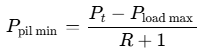
For example, with Pload max = 170 bar, Pt = 325 bar, and R = 8:1, Ppil min equals (325 − 170) / (8 + 1) ≈ 17.2 bar, safely exceeding a ≥17 bar brake release pressure; where system working pressures exceed brake seal limits, a pressure-reducing cartridge protects the brake port55.
Spring-Applied Hydraulically-Released (SAHR) multi-disc brakes: Crane hoist winches and slewing drives use fail-safe SAHR wet multi-disc brakes14. Heavy internal springs mechanically clamp alternating friction and steel discs whenever controls return to neutral, electrical power fails, or hydraulic pressure drops23. Supplying pilot or charge oil to an internal release piston compresses the springs to permit shaft rotation55. Required release pressures scale with brake architecture, ranging from ≥17 bar in compact integrated motor-brake manifolds55 up to figures such as 1,500 psi (~103 bar) referenced in heavy-duty SAHR brake service documentation57.
3. Safety Interlocks & Safe Load Indicators (SLI)
Because crane overturning moment rises directly with horizontal working radius, a Safe Load Indicator (SLI)—also designated a Load Moment Indicator (LMI) or Rated Capacity Indicator (RCI)—continuously compares active load moment against the certified capacity chart5. A standard SLI processor combines inputs from a boom-angle sensor at the boom pivot, a boom-length sensor (such as an internal cable-reel transducer on telescopic booms), and load sensors—either dual hydraulic pressure transducers monitoring bore and rod pressures in the luffing ram, structural load pins measuring tension on lattice-boom pendant lines, or direct hook load cells10. The operator console displays live hook load, allowable SWL at the current radius, percentage capacity, boom angle, length, and radius, and logs lifting cycles10. When a lift approaches capacity, visual and audible alarms activate; upon reaching cut-out, relay outputs block solenoid commands for overload-aggravating movements (hoist-up, boom-down, and telescope-out) while leaving recovery movements (hoist-down, boom-up, and telescope-in) operational so the operator can safely reduce moment10.
Hoist, luffing, and slewing limit switches: Anti-Two-Block (A2B / ATB) upper hoist limit switches protect against two-blocking, where the hook block is drawn into the boom tip sheaves and risks snapping the wire rope [90, 95, 96]. A typical A2B assembly suspends a weighted lever switch by a galvanized chain beneath the boom head (using IP65 or Ex-certified wired or wireless units); when the rising hook block lifts the counterweight, the switch trips to trigger alarms and interrupt hoist-up and telescope-out, with wired variants designed to fail-safe if the cable severs10. Alongside A2B switches, rotary geared limit switches mechanically driven off the winch drum shaft count drum revolutions to enforce both the upper hoist limit and the lower hoist limit, halting payout while safety wraps remain on the drum so the rope anchor never carries suspended load10. Boom-angle limit switches stop luffing at minimum and maximum design angles, while slew limit switches restrict rotation sectors near ship superstructures or deck hazards8. On davit winches, upper electrical limit switches likewise cut winch power if a boat is hoisted past its stowage stop8.
Slack-wire switches and manual emergency lowering valves: The technical manuals, regulatory circulars, and safety-equipment guides reviewed here document A2B switches, rotary drum limits, angle stops, and slew limits in detail8, but contain no engineering specifications or circuit schematics for deck-crane slack-wire (loose-rope) switches or crane manual emergency lowering bypass valves (only sea-state wire slackening phenomena61 and davit manual lowering mechanisms are covered). By contrast, manual emergency lowering on lifeboat and rescue boat davits is explicitly standardized: crews initiate controlled gravity descent during ship blackouts by lifting the winch counterweight brake arm locally at the deck winch or via a stainless-steel remote-control wire routed inside the survival craft, while turning single-arm davits outboard via hydraulic accumulators or manual hydraulic hand pumps8.
4. Lifesaving & Rescue Boat Davits (SOLAS Chapter III)
Under SOLAS Chapter III and LSA Code Section 6.1, survival craft and rescue boat launching appliances must safely deploy fully equipped craft (with full complement or operating crew) under unfavorable conditions of up to 10° trim and up to 20° list either way—and for oil, chemical, and gas tankers whose final angle of heel exceeds 20°, at that final damaged angle of heel on the lower side taking the final damaged waterline into account6. Under LSA Code 6.1.1.3, launching must rely solely on gravity or stored mechanical power independent of ship power supplies (an exception permits manual one-person turning out and hoisting on cargo-ship non-survival rescue boats weighing ≤700 kg fully equipped with engine and without crew, provided crank effort is ≤160 N at ≤350 mm crank radius and bowsing lines hold the boat alongside)7. Fully loaded lowering speed (S, in m/s) must satisfy LSA Code 6.1.2.87:

where H is the vertical distance in metres from the davit head to the waterline in the lightest sea-going condition; fully equipped craft without persons must still lower at ≥70% of that required speed (LSA Code 6.1.2.9)7. For recovery, LSA Code 6.1.1.9 requires rescue boat davits to feature a powered winch capable of hoisting the rescue boat with its full complement and equipment at ≥0.3 m/s (rising to ≥0.6 m/s with 6 persons and equipment for fast rescue boats under LSA Code 6.1.7.5)7.
Davit architectures: Gravity luffing-arm / pivoting davits carry conventional or enclosed twin-fall lifeboats on articulated arms that swing outboard under gravity and pay out dual wire falls33 (note that detailed kinematic comparisons between pivoting trunnion-arm versus trackway-rolling gravity davits are not present in the reviewed sources). Single-arm slewing davits, widely fitted for rescue boats and davit-launched liferafts (and often dual-rated as harbour provision cranes), comprise a deck-welded pedestal, slewing bearing, slewing tray, hydraulic slewing drive (hydraulic motor, wet-disc brake, planetary reducer, pinion), and an electric/manual winch fitted with a one-way roller clutch14. Under ship power, the electric motor drives hoisting through the one-way clutch (which locks instantaneously against reverse drop if power fails), while a small HPU slews the jib and charges a hydraulic accumulator monitored by a low-pressure alarm8. In dead-ship conditions, stored accumulator pressure slews the boat outboard—vendor specifications (Jinbo Marine) list ≤110° stored-power slewing at 0.6–0.8 rpm and wire lowering speeds of 40–60 m/min—backed by a manual hydraulic hand pump8. Free-fall stern ramps replace falls entirely during launch: the enclosed boat slides off an inclined stern skid under gravity, engineered per LSA Code 6.1.4.2 to clear the hull at up to 10° trim and 20° list while protecting occupants from excessive impact acceleration6.
Centrifugal speed-limiting brakes: Both gravity davit winches and single-arm slewing davits rely on enclosed mechanical centrifugal brakes paired with a counterweight-actuated manual holding brake8. When the operator lifts the deck brake lever or pulls the boat's remote-control wire spool, the one-way clutch isolates the electric motor and gravity drives drum rotation8. As speed increases, centrifugal friction blocks expand outward against springs into a fixed shell, capping descent speed smoothly regardless of load or ambient temperature14. Releasing the remote wire or deck lever drops the counterweight, engaging the friction brake to arrest lowering8.
Off-load vs. on-load release hooks & hydrostatic interlocks: Off-load release disengages hooks only once the boat is fully waterborne and load comes off the falls (including single-fall automatic waterborne hooks tested with a 200 kg dummy load lowered to the ground under MSC.402(96))21. Twin-fall lifeboats also carry on-load release gear capable of opening while still suspended in emergencies such as a jammed lowering sequence21. Following fatal inadvertent drop accidents, SOLAS Regulation III/1.5 (in force 1 January 2013, requiring replacement of non-compliant hooks by 1 July 2019) and amended LSA Code 4.4.7.6.4–4.4.7.6.6 enforce strict mechanical stability and interlocks64. Closed hooks must transmit zero opening force from the boat's weight to the release linkage, and cam-locked hook tails must continue holding full SWL across up to 45° of cam rotation64. A hull-mounted hydrostatic interlock built with a ≥6× ultimate-strength safety factor physically blocks release-handle operation until buoyancy confirms the boat is afloat (often showing a green indicator inside the boat and resetting automatically upon re-hoisting)21. Bypassing the interlock for emergency on-load release demands multiple deliberate, sustained steps—such as opening or breaking a protective cover and shifting a manual bypass lever—while green Fall Preventive Devices (FPDs) (locking/maintenance pins) mechanically pin the hooks during maintenance and stowage and must be removed before launch21.
Launching System | Primary Power / Launch Energy | Dead-Ship Blackout Operation | Descent & Hook Release Control | Typical Shipboard Role |
|---|---|---|---|---|
Gravity luffing-arm davit | Gravity launch; powered winch recovery7 | Gravity turnout and lowering independent of ship power7 | Centrifugal + counterweight brake; on-load/off-load hooks with hydrostatic interlock21 | Twin-fall enclosed and conventional lifeboats21 |
Single-arm slewing davit | Electric winch + hydraulic slewing HPU8 | Stored hydraulic accumulator + manual hand pump + gravity lower8 | Centrifugal brake + remote wire spool; off-load or dual-release hook8 | Rescue boats, liferafts, optional harbour provisions15 |
Free-fall stern ramp | Gravity slide; hydraulic/winch recovery6 | Gravity ramp launch at up to 10° trim and 20° list6 | Inclined skid clearance & acceleration protection; 5-yr 1.1 × hook test7 | Stern-launched free-fall lifeboats6 |
5. Failure Modes, Dynamic Sea-State Loads & Inspection
Dynamic Amplification Factors (DAF) in offshore and swell lifts: When lifting from or onto moving supply vessels or through the splash zone, ship roll, pitch, and heave generate relative vertical velocity (VR) between the crane tip and load—producing acute wire tension spikes during upward tip acceleration and slackness followed by snap-loading on downward drop61. Under DNV-ST-0378 (Offshore and platform lifting appliances), engineers distinguish the operation-specific DAF (peak dynamic response divided by calm-water static reference load per DNV-RP-N103; offshore engineering guidance illustrates an uncompensated 1-DOF lift reaching 3.2× versus 1.28× with a shock absorber, explicitly noting this is illustrative rather than an upper bound)61 from the crane's design dynamic factor (ψ) calculated from hook stiffness (C), working load (W), gravity (g), and relative velocity (VR)17:
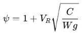
DNV-ST-0378 mandates a minimum floor of ψ ≥ 1.3 for offshore cranes handling loads outside the vessel up to 2,500 kN working load, tapering linearly to 1.1 at 5,000 kN and remaining 1.1 above 5,000 kN17. By comparison, sheltered/platform cranes use a 1.15 floor up to 2,500 kN, smaller subsea cranes may adopt ψ ≥ 1.7 for significant wave heights Hs ≤ 2 m (requiring no load chart), and a DNV-ST-0378 Type Approval Certificate for a 7,000 kg personnel-lifting winch specifies DAF = 1.617. When ψ exceeds 1.33, DNV-ST-0378 proof-load tables apply a reference SWL of 0.75 × ψ × SWL17.
Slewing ring bearing wear and bolt fatigue: Slewing bearings (single-row ball, double-row ball, cross-roller, or three-row roller rings) carry severe cyclic overturning moments11. P&I Club loss-prevention bulletins report that lack of greasing and inadequate monitoring are the principal causes of catastrophic slewing-bearing failure—affecting single-ball-race cranes most frequently, though double-ball-race and roller bearings also fail—compounded by torn sealing bellows and rough practices such as slant pulling or load swinging11. Retaining bolts securing inner and outer bearing races simultaneously accumulate high-cycle fatigue, prompting periodic torque checks every 3 to 12 months (depending on maker), paint-marking inspected bolts, and non-destructive testing (NDT) of removed bolts prior to 5-year load tests11. To measure raceway clearance growth directly, crews conduct rocking tests 3 months after ship delivery (per maker inspection schedules) and every 6 months thereafter across four orthogonal headings (fore, starboard, aft/stern, port) under no-load conditions, zeroing a magnetic-base dial gauge at minimum reach (jib raised) and recording deflection after luffing out to maximum reach69. Manufacturer standards such as MHI mandate bearing replacement if axial deflection exceeds +3.0 mm from the newbuild baseline (using 0.6 mm if initial records are missing), while slewing-bearing industry guidance treats <1.5 mm as generally serviceable and 2.0–3.0 mm as severe fatigue indicating raceway surface-hardening collapse; grease purged at four sampling points should also be analyzed for metallic wear particles11.
Wire rope deterioration and hydraulic oil overheating: Davit falls commonly employ galvanized, non-rotating fiber-core steel wire rope (e.g., 18×19+FC construction) and undergo annual checks for kinks, corrosion, lubrication, and sheave alignment under MSC.402(96), with mandatory renewal at least every 5 years—or sooner if deteriorated14. However, the regulatory circulars and technical sources reviewed here do not specify forensic inspection metrics or quantitative discard thresholds for internal wire-core corrosion or bird-caging strand distortion. Meanwhile, hydraulic oil overheating frequently degrades open-loop fixed-pump cranes when continuous idle circulation, valve throttling, and relief-valve pressure dumping convert hydraulic power into heat, accelerating fluid breakdown and seal failure25. Adopting load-sensing variable-displacement pumps, sizing reservoirs for adequate heat rejection, and maintaining functional 3–5% cooling bleed in closed-loop flushing valves prevents thermal degradation26.
Statutory 5-year overload and proof-load testing: Cargo/deck lifting appliances (SOLAS II-1/3-13, MSC.1/Circ.1663, DNV-ST-0378) and lifesaving launching gear (SOLAS III/20, LSA Code 6.1, MSC.402(96)) undergo calibrated proof-load testing every 5 years (plus initial, post-major-repair, and annual thorough examinations) using test weights or certified water bags and calibrated load cells1.
Appliance / Gear Category | Governing Rules | Statutory Test Interval | Required Proof-Load Specification | Inspection & Overhaul Conditions |
|---|---|---|---|---|
Shipboard cranes (SWL ≤ 20 t) | SOLAS II-1/3-13, MSC.1/Circ.1663, DNV-ST-037817 | Initial, post-major repair, and every 5 years27 | 1.25 × SWL (scale by 0.75 × ψ × SWL if offshore ψ > 1.33)17 | Thorough exam by competent person; register & cert update1 |
Shipboard cranes (20 t < SWL ≤ 50 t) | SOLAS II-1/3-13, MSC.1/Circ.1663, DNV-ST-037817 | Initial, post-major repair, and every 5 years27 | SWL + 5 t (relief-limited hydraulic cranes ≥ SWL + 10%)17 | Annual thorough exams; permanent SWL marking27 |
Shipboard cranes (SWL > 50 t) | SOLAS II-1/3-13, MSC.1/Circ.1663, DNV-ST-037817 | Initial, post-major repair, and every 5 years27 | 1.10 × SWL17 | Thorough exam; slew-ring bolt NDT advised prior to test11 |
Loose gear (hooks, shackles, blocks, beams) | MSC.1/Circ.1663 Table 2, DNV-ST-0378 Table 14-217 | Before first use & after major repair31 | Hooks/shackles/chains: 2 × SWL (≤25 t), 1.22 × SWL + 20 t (>25 t). Single-sheave blocks: 4 × SWL (half head load). Multi-sheave: 2 × SWL (≤25 t), 0.933 × SWL + 27 t (25–160 t), 1.1 × SWL (>160 t). Beams: 2 × SWL (≤10 t), 1.04 × SWL + 9.6 t (10–160 t), 1.1 × SWL (>160 t)17 | Unique ID & SWL marking; segregate unmarked/defective gear74 |
Lifeboat/rescue davits, winches & release hooks | SOLAS III/20, LSA Code 6.1, MSC.402(96)7 | Factory static; annual empty; 5-yearly dynamic overload7 | Factory static: ≥2.2 × MWL (davit), ≥1.5 × MWL (brake). 5-yr dynamic: 1.1 × (craft + full complement/gear) abruptly braked at max lowering speed7; Flag static limits where applicable (e.g., ≤200% per Bermuda Notice)33 | Fall renewal ≤5 yrs; release hook dismantling, crack NDT, and brake/structure reinspection by Flag-authorized provider20 |
References
- Lifting Appliances Certificate and Cargo Gear Register | ISR, https://intlshipregistry.com/services/class-and-statutory/cargo-gears-and-lifting-appliances-certification/
- ATEX zones explained — Zone 0, 1, 2, 20, 21, 22, https://www.enclosurecompany.com/guides/atex-zones
- GUIDELINES FOR HAZARDOUS AREA CLASSIFICATION AND, https://www.ccs.org.cn/ccswzen//file/download?fileid=201950000000000943
- Offshore Crane Types Compared: Lattice, Knuckle, Heavy-Lift, https://nodynamics.com/knowledge-hub/offshore-crane-types/
- SAF-020 - THE REPUBLIC OF LIBERIA, https://www.liscr.com/marketing/liscr/media/liscr/online%20library/maritime/saf-020.pdf
- LIFE SAVING APPLIANCES (LSA) CODE: - Sea-Connect, https://sea-connect.com/assets/img/uploads/pdf/c34f010279c2a9edf1e9828de06899ed.pdf
- Section 6.1 — Launching and embarkation appliances - Vercel, https://solas-lsa-code.vercel.app/en/lsa/6.1/
- WME-SAD24 Slewing Davit (For Rescue Boat / Life Raft), http://westmarine.com.sg/products/davits/tech_specs/SAD24_TS.PDF
- Open vs Closed Loop Hydraulic Systems | PDF - Scribd, https://www.scribd.com/doc/292317778/Closed-vs-Open-Loop-Safety
- Anti Two Block Device and Crane Safe Load Indicator Guide, https://desimachines.com/crane-guide/safety-devices/
- Crane Slewing Gear Maintenance and Rocking Tests, https://www.westpandi.com/getattachment/9121a166-3d88-4ea1-841f-7839294b9e68/crane-slewing-gear-maintenance-and-rocking-tests.pdf
- How the Anti-Two-Block System Reduces Operator Error and, https://www.skyazul.com/blogs/how-the-anti-two-block-system-reduces-operator-error-and-protects-lifting-equipment
- Explosion Proof (ATEX) Crane | Hoist Built In-House | ABRA, https://www.abracrane.com/products/ex-proof-cranes
- Structure of Single Arm Davit | China Lifeboat Davit Manufacturers, https://www.newmarinelifeboat.com/Structure-of-Single-Arm-Davit-id3909180.html
- SAF21 Davit Operation Manual | PDF | Crane (Machine) - Scribd, https://www.scribd.com/document/863158713/71900-Rescue-Boat-Davit-Marine-Auxiliary-Manual
- Single Arm Slewing Davit - YSmarines, https://www.ysmarines.com/life-boat/single-arm-slewing-davit/
- DNV-ST-0378 (replaced DNV 2.22): Offshore Lifting Appliances, https://nodynamics.com/knowledge-hub/dnv-st-0378-lifting-appliances/
- NDSC-34 – Rescue Boat Davit - VIKING-life.com, https://www.viking-life.com/pim/downloads/DS_D00501011_NDSC-34_09092026.pdf?context=bWFzdGVyfHJvb3R8MzYzMjQ5fGFwcGxpY2F0aW9uL3BkZnxhR05oTDJobFppOHhNRFV5TVRVeE1UYzRPRFUzTkM5RVUxOUVNREExTURFd01URmZUa1JUUXkwek5GOHdPVEE1TWpBeU5pNXdaR1l8YTMxZmY0OTFkODVlZDllNzcxNmQ5NTBmZmRkYjJmYzAwMzVjZWIzNWI5OTg1MzU3MmRmY2FjMWM1NjY0ZDQ1MA
- Open Loop vs. Closed Loop Hydraulic Systems - Fast Flow Pumps, https://www.fastflowpump.com/open-loop-vs-closed-loop-hydraulic-systems-a-technical-comparison-for-industrial-applications/
- Davit five-yearly load test (SOLAS) explained | HydraulicsUAE, https://hydraulicsuae.com/guides/davit-five-year-load-test
- Understanding Hydrostatic Interlock Systems and Lifeboat On-load, https://bbc-smrmarine.com/understanding-hydrostatic-interlock-systems-and-lifeboat-on-load-off-load-release-mechanisms-n26.html
- What is an Anti Two Block Warning System?, https://www.cranewarningsystemsatlanta.com/faq
- MULTIPLE DISC BRAKES - Winnect Industrial, https://winnect-industrial.com/product-category/hydraulic-brake/
- Safe Crane Equipment – safecraneuk, https://safecraneuk.com/
- A Guide to Learn open loop vs closed loop hydraulic system, https://hydraflu.com/a-guide-to-learn-open-loop-vs-closed-loop-hydraulic-system/
- Open Loop vs Closed Loop Hydraulic Systems | IsoHydraulic, https://isohydraulic.com/open-loop-vs-closed-loop-hydraulic/
- New safety requirements for onboard lifting appliances from 1 ... - DNV, https://www.dnv.com/news/2025/new-safety-requirements-for-onboard-lifting-appliances-from-1-january-2026/
- New SOLAS Requirements for Lifting Appliances – Entry into force, https://marine-offshore.bureauveritas.com/newsroom/new-solas-requirements-lifting-appliances-entry-force-1-january-2026
- Lifting Appliances and Anchor Handling Winches - irclass.org, https://www.irclass.org/technical-circulars/lifting-appliances-and-anchor-handling-winches/
- Ship Loose Lifting Gear Inspection: Shackles & Slings, https://marineinspection.app/blog/ship-loose-lifting-gear-inspection-shackles-slings-guide
- Implementation of new SOLAS Regulation II-1/3-13 Lifting ... - Uracos, https://uracos.org/wp-content/uploads/2025/11/URC25026-Lifting-appliances-and-anchor-handling-winches_compressed.pdf
- RESOLUTION MSC.402(96) (adopted on 19 May 2016, https://wwwcdn.imo.org/localresources/en/KnowledgeCentre/IndexofIMOResolutions/MSCResolutions/MSC.402(96).pdf
- Ship LSA Davit & Load Test Inspection Guide, https://marineinspection.app/blog/ship-life-saving-appliance-davit-load-test-inspection
- IMO Resolution, MSC. 402(96) reg. maintenance, thorough, https://www.irclass.org/technical-circulars/imo-resolution-msc-402-96-reg-maintenance-thorough-examination-operational-testing-overhaul-and-repair-of-lifeboats-including-free-fall-lifeboats/
- Marine Cranes: Ultimate Guide (2026) - Ship Universe, https://www.shipuniverse.com/ultimate-guide-marine-cranes/
- Lifting & Handling product portfolio | NOV, https://assets.nov.com/NCP4N68N/at/v724fjqtsw2w3v4r24jmsq3q/Lifting_and_Handling_Product_Portfolio.pdf
- Offshore Cranes - Liebherr, https://www.liebherr.com/shared/media/maritime-cranes/downloads-and-brochures/brochures/offshore-cranes/liebherr-offshore-cranes-product-range_en.pdf
- offshore cranes - Marine Equipments Pellegrini S.r.l., https://www.offshoremarinecranes.com/upload/x388allegato1-2xoffshore-cranes-b-292.pdf
- Rescue Boat Slewing Davits | Life Saving | Solas Marine, https://seasafetymarine.com/product/rescue-boat-slewing-davits/
- A2B Limit Switch | Anti Two Block Switch for Crane Safety by Saras, https://www.sarasequipments.com/detail/automatic-safe-load-indicator-for-cranes/limit-switch-with-weight-for-hydra
- CRANES AND HOISTS FOR HAZARDOUS ENVIRONMENTS, https://www.konecranes.com/sites/default/files/download/hazardous_environments_en_brochure_2016_konecranes_0.pdf
- Explosion-Proof Overhead Crane: Specifications, ATEX Certification, https://www.voittocrane.com/blog/explosion-proof-overhead-crane
- How do ATEX requirements apply to offshore crane operations?, https://www.pat-kruger.com/how-do-atex-requirements-apply-to-offshore-crane-operations/
- Expertise in explosion protection - Specialised Lifting Service, https://slscranes.com.au/uploads/documents/expertise-in-explosion-protection.pdf
- Cranes and hoists for Explosive Environment, https://gepesdaru.com/en/product/cranes-and-hoists-for-explosive-environment/
- Explosion Proof Crane Specs, https://explosionproofcrane.com/specs/
- HAZARDOUS AREA GUIDE for ATEX & IECEx (Zones/Groups) - cmlex, https://www.cmlex.com/wp-content/uploads/hazardous-area-guide.pdf
- Open Loop vs Closed Loop Hydraulic Systems - Hydrath Power, https://hydrathpower.com/open-loop-vs-closed-loop-hydraulic-systems/
- Open Loop vs. Closed Loop Hydraulic Systems | Power Drives Inc, https://www.powerdrives.com/open-loop-vs-closed-loop-hydraulic-systems/
- Open‑Loop vs Closed‑Loop Control in Hydraulic Passenger Lifts, https://dhollandiasa.com/2025/10/29/open%E2%80%91loop-vs-closed%E2%80%91loop-control-in-hydraulic-passenger-lifts/
- The Difference Between Open Loop Vs Closed Loop Hydraulics., https://berendsen.com.au/news/the-difference-between-open-loop-vs-closed-loop-hydraulics/
- Counterbalance Valve In Forestry And Crane Equipment, https://hfdhydraulic.com/counterbalance-valve-in-forestry-and-crane/
- Hydraulic Counterbalance Valves: Beyond Basic Load Control, https://hfdhydraulic.com/hydraulic-counterbalance-valves-and-load-control/
- Load Holding Systems: Hose Burst Protection, https://www.marketfluxhq.com/news/Hydraulic_Safety_Valves/Counterbalance_Holding_Valves/How_do_load_holding_systems_prevent_load_drops_after_a_hose_burst.html
- DUAL COUNTERBALANCE WITH BRAKE RELEASE PORT, https://apps.boschrexroth.com/products/compact-hydraulics/ch-catalog/pdf/Dual_count_with_brake_release_port.pdf
- How Do SAHR Brakes Work? - Knott Brake, https://knottbrake.com/how-do-sahr-brakes-work/
- SAHR Brakes Manual PDF - Scribd, https://pt.scribd.com/document/326968689/SAHR-Brakes-Manual-pdf
- Over hoist A2b Limit Switch for crane Safe Load Indicator, https://www.safeloadindicatorindia.com/product/28363280/Over-hoist-A2b-Limit-Switch-for-crane-Safe-Load-Indicator
- Crane Anti Two Block Switch & Display Options, https://store.bodetechnicalservices.com/blogs/news/crane-anti-two-block
- Anti-Two Block (ATB) Warning Systems - Rayco Wylie Systems, https://raycowylie.com/anti-two-block-devices/
- Dynamic Amplification Factor (DAF) in Offshore Lifting, https://nodynamics.com/knowledge-hub/dynamic-amplification-factor/
- Single Arm Davit - Life Saving Equipments, http://rescueboatdavit.com/single-arm-davit/
- Single Arm Slewing Davit - Jinbo Marine, https://www.jinbomarine.com/Single-Arm-Slewing-Davit.html
- Technical Information - ClassNK, https://www.classnk.or.jp/hp/pdf/tech_info/tech_img/T862e.pdf
- Hydrostatic interlock servicing - ARA Marine, https://aramarine.com.au/capabilities/lifeboats-and-davits/hydrostatic-interlock-servicing/
- Lifeboat Release & Retrieval Systems - fma.fo, https://fma.fo/wp-content/uploads/2016/09/2011-03-Lifeboat-Release-Retrieval-Systems.pdf
- Dynamic Amplification Factor | Defintion by Offshore Energy Limited, https://offshoreenergyintl.com/glossary/dynamic-amplification-factor/
- TYPE APPROVAL CERTIFICATE - DNV, https://approvalfinder.dnv.com/api/approval/document?id=TAS000056C
- Crane Slew Bearing Rocking Test, https://www.slewbearingtec.com/crane-slew-bearing-rocking-test.html
- Slewing bearing for Deck Crane Necessity of periodical Rocking test, https://www.mhi.com/products/ship/pdf/as-dc08-003.pdf
- rocking test procedure - sailorsview, https://sailorsview.files.wordpress.com/2014/11/rock-test.pdf
- MSC.402(96) inspection intervals: lifeboats & davits - OJ Safety, https://ojsafety.com/faq/msc-40296-inspection-intervals-lifeboats-davits/
- Lifeboat Static and Dynamic Load Tests: A Practical SOLAS, https://www.newmarinelifeboat.com/Lifeboat-Static-and-Dynamic-Load-Tests-A-Practical-SOLAS-Compliance-Guide-id41368565.html
- MSC.1/Circ.1663 - Guidelines for Lifting Appliances, https://www.iomshipregistry.com/media/pe0np5qv/msc1-circ1663-guidelines-for-lifting-appliances.pdf
- SOLAS Lifting Appliances Regulation 2026: Manual Ready?, https://vragamarine.com/solas-lifting-appliances-regulation-2026/
- 3 Dynamic Winch Brake Test - imorules, https://www.imorules.com/GUID-90E5B65A-D504-469A-A521-5038C6012A1E.html