1. What Is This Ship?
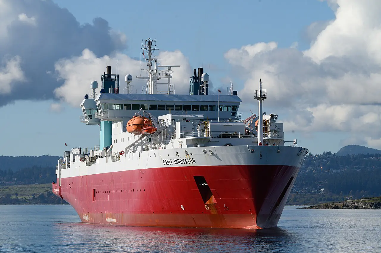
A cable-laying vessel (CLV) is a highly specialized offshore vessel engineered for the complex, multi-stage task of deploying, maintaining, and repairing submarine cables on the seabed. These cables are the invisible lifeblood of the modern global economy, forming the primary backbone of transoceanic telecommunications networks and providing the critical connection for offshore renewable energy, such as massive wind farms, to the terrestrial power grid.
Unlike standard cargo ships, tankers, or even general-purpose construction vessels, a CLV is essentially a massive, mobile industrial plant. Its primary function is not the transport of goods, but the extreme precision management of tension and the controlled deployment of heavy, sensitive cables over vast distances and highly variable seabed topographies. The stakes are exceptionally high; a single error in tension or a slight deviation in the vessel’s track can lead to catastrophic cable damage, costing millions in repairs and causing significant service outages for millions of users.
The distinction between a CLV and other offshore vessels lies in several key areas:
- Storage Capacity: The ability to carry thousands of kilometers of cable in massive, specialized rotating drums (carousels) or turntables.
- Tension Control: Highly sophisticated tensioning systems that ensure the cable is neither too tight (risking breakage) nor too slack (risking tangling or incorrect laying depth).
- Positioning Precision: The requirement for extreme station-keeping through advanced Dynamic Positioning (DP) systems, often at the DP3 level, to maintain exact tracks and positions in heavy seas.
- Subsea Intervention: The integration of heavy-duty burial and inspection tools, such as ploughs, vertical injectors, and Remotely Operated Vehicles (ROVs).
2. Mission and Operations
The operational life of a cable-laying vessel is a complex sequence of highly technical phases, each requiring specialized equipment and precision coordination between the marine crew and the technical installation team.
Route Survey and Clearance
Before any cable is laid, a thorough survey of the intended route is conducted. This involves hydrographic and geophysical surveys using multi-beam echosounders and side-scan sonar to map the seabed in high resolution. The goal is to identify any potential obstacles—such as shipwrecks, rocky outcrops, existing cables, or discarded fishing gear—that could snag or damage the new cable. This phase ensures the “path of least resistance” is selected.
Cable Installation (Laying)
Once the route is cleared, the installation begins. The vessel follows a pre-programmed track, precisely controlled by its DP system. The cable is paid out from the onboard storage (carousels or turntables) and passed through a series of specialized tensioners. These tensioners act as the interface between the vessel and the seabed, maintaining a constant, safe tension on the cable as it is deployed. The speed of deployment is carefully managed to ensure the cable is laid at the correct tension and depth, accounting for the vessel’s movement and the seabed’s profile.
Cable Burial (Trenching and Protection)
In many environments, particularly near shore or in areas with high maritime activity, cables must be buried beneath the seabed to protect them from anthropogenic threats (such as fishing trawls and anchors) and natural forces (such as seabed currents and shifting sands). CLVs use several methods for this:
- Ploughs: These are heavy, mechanical devices towed behind the vessel. They cut a trench in the seabed and simultaneously lay the cable into it, often covering the cable with a layer of sediment in a single pass.
- Vertical Injectors: This method uses high-pressure water jets to fluidize the seabed, allowing the cable to sink into the newly created “softened” trench. This is often more effective in certain types of sediment.
- Rock Saws: In cases where the seabed consists of hard rock or very consolidated sediment, specialized rock saws are used to cut a trench.
- ROV-based Trenching: For highly complex or sensitive areas, Remotely Operated Vehicles (ROVs) equipped with specialized trenching tools can be deployed to perform localized burial.
Post-Lay Inspection and Monitoring
After the cable is laid and buried, it is crucial to verify its condition and position. This is known as Post-Lay Inspection (PLI). Using ROVs equipped with high-definition cameras and sonar, technicians inspect the cable to ensure it has been buried to the required depth and that no sections are exposed or improperly positioned. This phase is critical for long-term reliability and for creating an accurate “as-laid” map for future maintenance.
Maintenance and Repair
Cables are subject to wear and damage over their decades-long lifespans. Specialized “repair vessels” are part of the CLV fleet, designed for rapid response. When a fault is detected (often via signal monitoring), the repair vessel is deployed to the location. They use grapnels or ROVs to locate and recover the broken cable ends, perform a “jointing” operation (splicing the cables back together in a controlled, clean environment on board), and then re-lay the repaired section back onto the seabed.
3. Hull, Size, and Design
The design of a CLV is a specialized engineering challenge, balancing the need for massive storage, stable operations, and high-tech positioning.
Cable Storage Architecture: Carousels vs. Turntables
The most defining feature of a CLV is how it carries its payload.
- Carousels: These are massive, circular, rotating drums located within the vessel’s hull. They are designed for high-capacity, continuous deployment of long-distance cables. Carousels allow for the storage of thousands of kilometers of cable in a compact, integrated format, which is essential for transoceanic telecommunications. However, they are large and significantly impact the vessel’s center of gravity and stability.
- Turntables: These are smaller, multi-platform rotating systems. They are often used for “bundle laying,” where multiple cables of different types or sizes need to be stored and deployed simultaneously. Turntables offer more flexibility in handling different cable diameters but generally have lower overall storage capacity than a large carousel.
Dimensions, Stability, and Draught
CLVs are typically large, heavy, and designed for high stability to provide a steady platform for delicate operations.
- Length: Vessels can range from approximately 100 m for specialized repair/shallow-water ships to over 200 m for large-scale installation vessels.
- Breadth: They are often wider than standard ships to accommodate the massive deck equipment and to provide a wider beam for improved stability during heavy lifting or trenching.
- Draught: This is a critical design parameter. “Shallow-water” or “beaching” vessels are designed with a shallow draught to allow them to operate close to shore and even approach the beach for the “shore end” of a cable installation. Conversely, deep-sea vessels may have a deeper draught to accommodate larger hulls, more powerful engines, and more extensive fuel and cable storage.
4. Propulsion and Engines
Propulsion for a CLV must provide not only transit speed but also extreme, high-precision maneuverability and the ability to maintain a perfect station in even the most challenging sea states.
Azimuth Podded Propulsion (Azipods®)
Modern, high-specification CLVs almost universally utilize Azipod® propulsion systems. Unlike traditional shaft-driven propellers, Azipods are 360-degree rotating electric propulsion units mounted in pods beneath the hull.
- Maneuverability: Because the pods can rotate in any direction, they provide full thrust in all directions, allowing the vessel to move sideways, rotate on its axis, and respond instantly to environmental forces.
- Efficiency and Reliability: Azipods are more efficient than traditional systems and require less internal space, which can be reallocated to cable storage. Being gearless (the electric motor is housed within the pod) also reduces mechanical complexity and maintenance requirements.
Thruster Configuration and Station-Keeping
To achieve the level of precision required for cable laying, CLVs combine their main propulsion (Azipods) with multiple bow and stern thrusters. This combination allows the vessel to control its position across the three primary axes: surge (forward/aft), sway (port/starboard), and yaw (rotation). This capability is essential for following a precise, pre-programmed cable track.
Engine Redundancy and Power Management
The power requirements for a CLV are enormous and highly dynamic. The vessel must simultaneously power its propulsion, its Dynamic Positioning (DP) system, its heavy-duty cable tensioners, and its subsea burial tools.
- Redundancy: To ensure safety and prevent loss of position, engines are typically arranged in multiple, independent sets. This redundancy is a core requirement for DP2 and DP3 classification.
- Dynamic Power Demand: The power load can spike suddenly when a tensioner engages or when the vessel encounters a heavy gust of wind. Advanced power management systems are used to balance these loads and ensure that critical systems, like the DP, always have priority.
5. Electrical System and Power
The electrical architecture of a CLV is as critical to its mission as its hull or engines. The vessel must manage massive, rapidly changing electrical loads while maintaining absolute reliability.
The Shift to Onboard DC Grids
A major trend in modern CLV design is the move from traditional AC (alternating current) electrical grids to Onboard DC (direct current) Grids.
- Efficiency: DC grids are more efficient at managing power from diverse sources, such as diesel generators and energy storage systems.
- Response Time: They are significantly better at handling the extreme, instantaneous power spikes required by cable tensioners and DP thrusters, which can otherwise cause voltage drops and instability in an AC system.
Energy Storage Systems (ESS)
Many state-of-the-art CLVs now incorporate large-scale Energy Storage Systems (ESS), such as advanced battery banks.
- Peak Shaving: The ESS acts as a buffer, providing immediate bursts of power during high-demand events (like a sudden DP correction) and absorbing excess energy during low-demand periods.
- Fuel Efficiency: By optimizing the load on the main diesel generators, the ESS can significantly reduce fuel consumption and overall carbon emissions, helping vessels meet increasingly stringent environmental regulations.
Integrated Automation
A CLV’s electrical system is overseen by a highly sophisticated Integrated Automation System (IAS). This system provides real-time monitoring and control of power generation, distribution, and consumption, ensuring that the vessel’s complex “energy ecosystem” remains stable and efficient during even the most demanding operations.
6. Equipment and How It Is Used
A CLV is characterized by its highly specialized, heavy-duty machinery. The following equipment is essential for modern cable operations:
| Equipment | Function | Detailed Description |
|---|---|---|
| Cable Carousel | Primary Cable Storage | A massive, rotating drum that holds thousands of kilometers of cable, allowing for continuous, high-capacity deployment. |
| Turntables | Multi-Cable Storage | Rotating platforms used for storing and deploying multiple cables or smaller lengths, providing flexibility for bundle laying. |
| Cable Tensioner | Tension Management | A critical system that maintains constant, controlled tension on the cable during payout to prevent breakage or damage. |
| ROV (Remotely Operated Vehicle) | Subsea Intervention | An underwater robot used for high-resolution inspection, seabed mapping, and precision burial tasks. |
| Plough | Mechanical Burial | A heavy, towed device that cuts a trench and lays the cable into it in a single, efficient operation. |
| Vertical Injector | Fluidized Burial | A system that uses high-pressure water jets to create a soft trench, allowing the cable to sink into the seabed. |
| Rock Saw | Hard-Seabed Trenching | A specialized tool designed to cut through rock or extremely hard sediment for cable protection. |
| Grapnel | Cable Recovery | Specialized heavy-duty hooks used to locate and retrieve broken or lost cable ends from the seabed. |
| Dynamic Positioning (DP) System | Precision Station-Keeping | A computer-controlled system using sensors and thrusters to maintain an exact position and heading. |
7. Navigation, Communications, and Safety
The ability to navigate with millimeter-level precision and maintain constant communication with subsea assets is what separates a CLV from a standard vessel.
Dynamic Positioning (DP) Systems
The DP system is the heart of a CLV’s station-keeping capability. It operates on a continuous, high-speed feedback loop:
- Sensing: The system uses a variety of sensors (GPS, hydroacoustics, wind sensors) to determine the vessel’s exact position and the environmental forces acting upon it.
- Calculating: A high-performance computer uses a complex mathematical model of the vessel’s hull and propulsion to calculate the exact amount of corrective thrust needed.
- Acting: The computer issues commands to the thrusters (Thrust Allocation Logic) to apply the required force.
The DP Hierarchy:
- DP1: Provides basic positioning but has no redundancy; a single component failure can cause a loss of position.
- DP2: Offers significant redundancy; the vessel can maintain its position even if a single active component (like a generator or thruster) fails.
- DP3: The gold standard for high-risk operations; it provides full physical and electrical separation of systems. A DP3 vessel can maintain its position even during a catastrophic event, such as a fire or flood in a single compartment.
Position Reference Systems
To ensure absolute accuracy, CLVs use multiple, redundant position reference systems:
- DGPS (Differential GPS): The primary global positioning method.
- Hydroacoustic Systems: Using sound waves to determine position relative to sensors on the seabed.
- USBL (Ultra-Short Baseline): Ideal for ROVs and localized, high-precision tasks.
- LBL (Long Baseline): Provides extremely high accuracy in deep water by using a pre-installed grid of acoustic transponders on the seabed.
- Taut Wire: A physical wire lowered to the seabed, providing a highly stable and reliable reference point.
Communications and Safety
Effective communication is vital for coordinating between the bridge, the cable deck, and the subsea ROVs. This is achieved through a combination of satellite communications (VSAT) for long-range data and acoustic links for underwater assets. Safety is maintained through rigorous risk assessments, continuous environmental monitoring (sonar/wind), and strict adherence to international maritime safety standards.
8. Crew and Organization
The crew of a CLV is a complex, multi-disciplinary team, combining traditional maritime expertise with highly specialized technical knowledge.
Command and Structure
The vessel operates under the ultimate command of the Master, who is responsible for the overall safety and navigation of the ship. However, the operational focus is split between two distinct but highly integrated departments:
- Marine Department: Responsible for navigation, vessel stability, propulsion, and general maritime safety.
- Project/Technical Department: Responsible for the actual cable installation, engineering, subsea operations, and technical maintenance.
Key Roles and Responsibilities
The crew is divided into several specialized groups:
- Marine Crew: Includes the Master, Officers, Engineers, and Deckhands, all focused on the vessel’s safe operation.
- Cable & Installation Crew: Specialists such as Cable Engineers, Carousel and Tensioner Operators, and Jointing Supervisors, who manage the delicate process of cable deployment.
- Subsea & Technical Crew: Includes ROV Pilots, Subsea Supervisors, Surveyors, and Offshore Electricians, who manage the underwater intervention and technical systems.
- Project Management: Shore-based and vessel-based Project Managers and HSE (Health, Safety, and Environment) Coordinators ensure the mission meets all technical and safety requirements.
9. Certificates and Training Requirements
Working on a CLV is a highly specialized career that requires a rigorous combination of international maritime certifications and mission-specific technical training.
| Category | Certification/Requirement | Description |
|---|---|---|
| Mandatory Maritime (STCW) | STCW Certification | International standards for training, certification, and watchkeeping for all seafarers. |
| ENG1 Medical | Mandatory seafarer medical certification to ensure fitness for duty. | |
| Security Awareness | Compliance with STCW VI/6 standards for maritime security. | |
| Offshore Safety | BOSIET / HUET | Basic Offshore Safety Induction and Emergency Training / Helicopter Underwater Escape Training. |
| Specialized Technical | DP Induction / Certificate | Critical training for anyone involved in the operation of Dynamic Positioning systems. |
| COMPEX | Certification required for working in potentially explosive/electrical environments. | |
| GWO Standards | Global Wind Organisation standards, essential for working on offshore wind projects. | |
| IMCA Guidelines | Compliance with International Marine Contractors Association standards for offshore operations. | |
| Role-Specific Quals | Specialized training for ROV piloting, cable jointing, and hydrographic surveying. |
10. Regulations, Class, and Inspections
CLVs operate in a highly regulated global environment, subject to international laws and strict industry standards to ensure safety and environmental protection.
International Maritime Organization (IMO) Conventions
All CLVs must comply with core international maritime regulations:
- SOLAS (Safety of Life at Sea): Sets the global standards for vessel construction, equipment, and emergency procedures.
- MARPOL (Marine Pollution): Governs the prevention of pollution from ships, covering oil, sewage, garbage, and ballast water.
- COLREGs: The international rules for preventing collisions at sea.
- ISM Code: The International Safety Management Code, which mandates that every vessel operates under a rigorous Safety Management System (SMS).
Classification Societies
To verify that they meet the highest technical and safety standards, CLVs are “classed” by recognized international societies such as DNV, ABS, Lloyd’s Register (LR), or Bureau Veritas (BV). These societies conduct regular, stringent inspections and audits of the vessel’s hull, machinery, and systems.
Operational Safety and Compliance
- SIMOPS (Simultaneous Operations): A critical safety protocol used to manage the risks of multiple high-stakes activities (e.g., cable laying and ROV diving) occurring at once.
- Risk Assessment & Toolbox Talks: Mandatory procedures where crews identify potential hazards and agree on mitigation strategies before any high-risk task begins.
11. Notable Shipyards, Operators, and Example Vessels
The CLV market is characterized by a few dominant global players and highly specialized shipyards capable of building these complex assets.
Leading Operators
- Jan De Nul: A Belgian leader in large-scale offshore installation.
- Nexans: A major French operator with advanced bundle-laying capabilities.
- Prysmian: A global leader in both cable manufacturing and specialized installation.
- Orange Marine: A top-tier specialist in cable repair and maintenance.
- SubCom: A major global player in deep-sea telecommunications infrastructure.
Example Vessels
| Vessel Name | Operator | Notable Feature/Capability |
|---|---|---|
| Nexans Electra | Nexans | Next-generation vessel capable of bundle laying up to 4 cables. |
| Ulisse | Prysmian | Specialized for shallow-water, beaching, and repair operations. |
| NKT Victoria | NKT | Advanced Azipod propulsion and Onboard DC Grid technology. |
| Fleeming Jenkin | Jan De Nul | Massive 215-meter vessel designed for large-scale installation. |
| Sophie Germain | Orange Marine | Highly capable, modern cable repair and installation vessel. |
| KDDI Cable Infinity | KDDI | Specialized Japanese-owned vessel for telecommunications. |
12. Environment and Future Outlook
The future of the cable-laying industry is being shaped by two massive global trends: the energy transition and the digital revolution.
The Renewable Energy Boom
The global shift toward offshore wind energy is creating unprecedented demand for CLVs. The industry is rapidly evolving to meet this need, with a focus on vessels capable of “bundle laying” (installing multiple cables at once) and managing the higher voltages required for massive offshore wind farms. There is also a powerful push toward decarbonization, with new vessels integrating hybrid power, energy storage, and more efficient propulsion to meet zero-emission targets.
The Digital Imperative
As global data consumption continues its exponential growth, the demand for high-capacity, ultra-reliable subsea fiber-optic cables is higher than ever. This drives the need for CLVs that can operate with extreme precision in the world’s deepest and most challenging ocean environments.
Automation and Robotics
The industry is moving toward a future of increased automation. From AI-driven DP systems to more autonomous and capable ROVs, the goal is to reduce human exposure to high-risk environments while simultaneously increasing the precision and efficiency of subsea operations.
13. Facts, Records, and Common Misconceptions
Common Misconceptions
- “Cable layers are just regular ships with winches.” They are among the most technologically advanced and complex vessels in existence, featuring integrated power grids, DP3 systems, and massive specialized storage.
- “All cables are buried deep.” While burial is common, some cables (especially in very deep water) are laid directly on the seabed, relying on their own weight and specialized protection for safety.
- “Repairing a cable is a simple task.” It is an extremely high-stakes, precision operation that requires specialized subsea intervention and highly skilled technical teams.
Key Facts
- A single cable-laying campaign can span months and involve the deployment of thousands of kilometers of cable.
- The “jointing” of a submarine cable is one of the most delicate and technically demanding operations in the entire maritime industry, often requiring a clean-room environment on board.
14. Glossary
- Azipod: A 360-degree rotating podded propulsion unit.
- BOSIET: Basic Offshore Safety Induction and Emergency Training.
- Bundle Laying: The simultaneous installation of multiple cables.
- Carousel: A large, rotating drum used for high-capacity cable storage.
- DP (Dynamic Positioning): A computer-controlled system for maintaining vessel position.
- DP3: The highest class of dynamic positioning, providing full redundancy and separation.
- Heave, Pitch, Roll: The three degrees of motion NOT controlled by DP.
- LBL (Long Baseline): A high-accuracy acoustic positioning system using seabed transponders.
- ROV (Remotely Operated Vehicle): An underwater robot used for subsea tasks.
- SIMOPS: Simultaneous Operations; managing multiple tasks safely in one area.
- STCW: International standards for maritime training and certification.
- Surge, Sway, Yaw: The three degrees of motion controlled by DP.
- Tensioner: A device used to maintain constant tension on the cable during deployment.
- USBL (Ultra-Short Baseline): An acoustic positioning system for localized precision.
15. Sources
- Prysmian - Ulisse Datasheet
- Nexans - Nexans Electra Technical Details
- ABB - NKT Victoria Marine Reference
- ABB - Azipod Propulsion Solutions
- Kongsberg - Dynamic Positioning Systems
- Maersk Training - How Dynamic Positioning Works
- Worldwide Recruitment Solutions - Cable/Pipelay Jobs
- Global Marine - Junior Systems Technician Role