1. Incident Overview and Key Facts
The capsize of the Alexander L. Kielland remains one of the most significant maritime disasters in the history of the North Sea oil industry. On March 27, 1980, the semi-submersible accommodation rig suffered a sudden and catastrophic structural failure that led to its rapid capsize during a period of heavy weather. The disaster resulted in the deaths of 123 people out of the 212 on board, making it the deadliest offshore accident in Norwegian history.
| Fact | Detail |
|---|---|
| Incident Date | March 27, 1980 |
| Vessel Name | Alexander L. Kielland |
| Vessel Type | Semi-submersible Accommodation Rig |
| Flag | Norway |
| Location | Ekofisk Field, North Sea |
| Fatalities | 123 |
| Outcome | Total Capsize and Loss of Vessel |
| Investigating Authority | Norwegian Commission of Inquiry (Havarikommisjonen) |
2. The Vessel and Crew Context
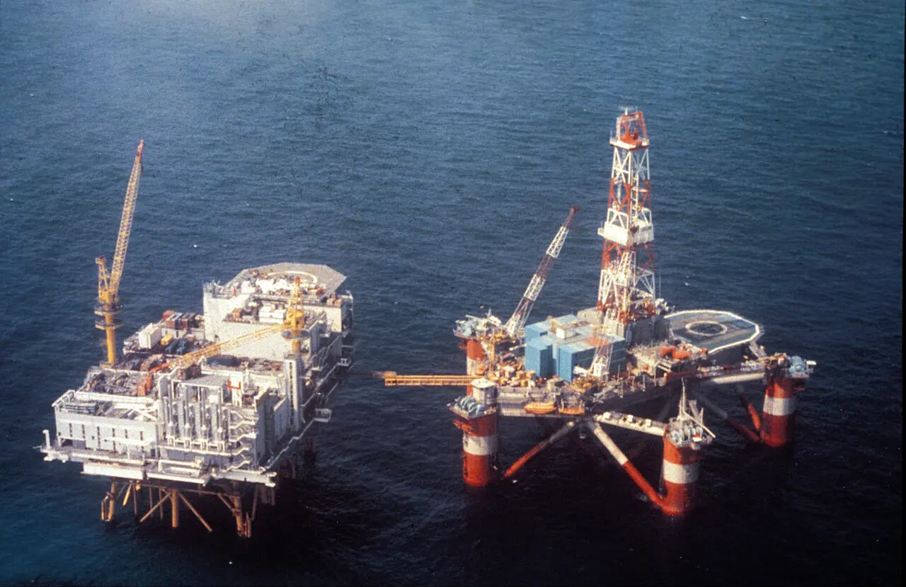
The Alexander L. Kielland was a large semi-submersible accommodation rig, designed to provide living quarters for workers operating in the burgeoning North Sea oil fields. Unlike many drilling rigs of the era, the Kielland was specifically engineered to support high concentrations of personnel, making its stability and structural integrity paramount.
Design Specifications
The rig featured a five-column design, supported by a complex network of tubular steel bracings that connected the vertical columns to the lower pontoons and the upper deck structure. This structural arrangement was intended to provide the necessary stiffness and buoyancy to withstand the extreme environmental loads characteristic of the North Sea.
Operational Profile
At the time of the accident, the rig was stationed in the Ekofisk field, one of the most productive areas of the Norwegian Continental Shelf (NCS). The crew consisted of approximately 212 persons, including engineers, technicians, and accommodation staff. The rig was operating in heavy seas, which placed significant cyclical stress on the structural members, particularly the bracings connecting the columns.
3. Chronological Timeline of Events
The disaster was not a single instantaneous event but a rapid progression of structural failures triggered by a long-standing, undetected defect.
- Pre-incident (1976–1980): A fatigue crack began to propagate in brace D-6. This crack originated from sub-standard welding and material defects at a hydrophone support attachment point during the rig’s construction.
- March 27, 1980, Early Morning: The rig was experiencing heavy North Sea weather. The cyclical loading from wave action accelerated the growth of the fatigue crack in brace D-6.
- The Moment of Failure: The fatigue crack reached a critical size, leading to the sudden brittle/ductile fracture of brace D-6.
- Seconds Later: With the failure of D-6, the remaining five bracings connected to Column D were subjected to immediate and massive overload. These braces failed in rapid succession through plastic collapse.
- Column Separation: Column D became completely separated from the main structure of the rig.
- Loss of Stability: The loss of Column D caused an immediate and severe shift in the vessel’s center of buoyancy and a massive increase in the heeling moment.
- The Capsize: The rig began to heel violently. As the angle of heel increased, progressive flooding occurred through openings and damaged compartments. The rig capsized completely in a matter of minutes, leaving the crew with almost no time to evacuate.
4. Technical & Hydrodynamic Failure Analysis
The failure of the Alexander L. Kielland was a multi-stage structural catastrophe, beginning with a localized material defect and culminating in a global stability failure.
4.1 The Initiating Event: Fatigue Failure of Brace D-6
The root cause of the disaster was a fatigue crack that developed in one of the primary structural members: the tubular bracing designated D-6, which provided support to Column D.
4.1.1 The Hydrophone Support Defect
The crack did not initiate in the main structural weld of the brace itself, but rather at a secondary attachment point. A circular hole had been gas-cut into the D-6 bracing to accommodate a hydrophone (a sonar device used for positioning control). This hydrophone was housed in a tube that was subsequently welded to the brace using a double fillet weld arrangement (one inside the brace and one outside).
The investigation revealed several critical flaws in this installation:
- Poor Surface Preparation: The hole made by gas cutting was not properly treated; it was not ground smooth, leaving a rough, stressed surface. Furthermore, the welding was performed on surfaces that still contained paint residue.
- Sub-standard Welding: The double fillet welds, which had a nominal throat thickness of 6 mm, were of extremely poor quality. Forensic analysis identified incomplete penetration, slag inclusions, and root cracks within the weld beads. The weld profile was also unsatisfactory, contributing to localized stress concentrations.
- Stress Concentration (Kt): Due to the poor geometry of the welds and the abrupt change in the cross-section of the brace, the stress concentration factor (Kt) at the hydrophone attachment was estimated to be between 2.5 and 3.0. For comparison, a standard, well-executed fillet weld typically exhibits a Kt of approximately 1.6.
4.1.2 Material Science and Lamellar Tearing
The failure was further exacerbated by the metallurgical properties of the materials used. The hydrophone tube itself possessed poor through-thickness ductility and tensile strength compared to the structural steel of the D-6 brace.
More critically, the investigation found evidence of lamellar tearing in the heat-affected zone (HAZ) of the weld. This type of cracking occurs in thick steel sections when high-strain welding processes cause separations along the planes of non-metallic inclusions (such as sulfides or oxides) within the steel. The combination of poor material quality and the high-stress welding process created a fertile ground for crack initiation.
4.1.3 Fatigue Propagation
The fatigue life of this specific connection was calculated to be in the range of only 0.7 to 5 years. Given the rig entered service in 1976, the crack had likely been propagating for several years before the final failure.
The crack growth followed a specific sequence:
- Initiation: Cracks started at two distinct sites near the fillet welds of the hydrophone support.
- Propagation: The cracks grew circumferentially around the D-6 bracing.
- Final Fracture: Once the crack reached approximately 60% to 70% of the circumference of the brace, the remaining cross-section could no longer support the operational loads, leading to a final, rapid fracture of the D-6 member.
4.2 Structural Collapse: Sequential Bracing Failure
The failure of brace D-6 triggered a catastrophic “domino effect” within the rig’s structural framework. Brace D-6 was one of six tubular bracings that connected Column D to the rest of the platform.
When D-6 failed, the structural load it had been carrying was instantaneously redistributed to the remaining five braces. This sudden transfer of force exceeded the ultimate strength of these members. They failed in rapid succession through plastic collapse (ductile overload), leading to the total separation of Column D from the main hull.
4.3 Stability Loss and Capsizing
The loss of Column D was a terminal event for the vessel’s stability. A semi-submersible rig relies on the symmetrical buoyancy and weight distribution of its columns to maintain an upright position.
The separation of a major column caused:
- Immediate Buoyancy Imbalance: The loss of buoyancy from Column D created a massive, asymmetric heeling moment.
- Dynamic Heeling: In the heavy seas present at the time, the rig was unable to recover from the initial list. The wave action acted on the now-unbalanced hull, driving the heel angle further.
- Progressive Flooding: As the rig reached extreme angles, water began to enter the structure through various openings, hatches, and potentially through damage sustained during the structural collapse. This led to the free surface effect, further reducing the metacentric height (GM) and accelerating the capsize.
The failure of the structural integrity of the bracing system directly led to the catastrophic loss of hydrodynamic stability.
5. Human Factors, Bridge/Engine Management, and Organizational Issues
While the physical cause was a fatigue crack, the root cause was a systemic failure in the design, construction, and quality assurance processes.
5.1 Design and Planning Errors
The decision to install the hydrophone support by welding a tube directly into a primary structural brace was a fundamental design oversight. The design failed to account for the extreme stress concentrations that such an insertion would introduce into a fatigue-critical member. There was a lack of structural redundancy; the rig was designed such that the failure of a single bracing member could lead to the loss of an entire column.
5.2 Fabrication and Quality Control Failures
The rig was constructed at a shipyard in Dunkirk, France. The investigation pointed to significant lapses in quality control during this phase:
- Inadequate Welding Oversight: The poor quality of the fillet welds, including the presence of slag and incomplete penetration, indicates that the welding was not performed or inspected according to professional standards.
- Failure of Inspection Protocols: The fact that these defects (and the resulting cracks) existed before the rig even left the shipyard, and yet were never detected during routine inspections or during the rig’s years of operation, highlights a failure in the non-destructive testing (NDT) and maintenance regimes.
- Improper Workmanship: The use of gas cutting without subsequent grinding and the welding of over paint residue are classic examples of poor workmanship that compromise structural longevity.
5.3 Regulatory and Organizational Context
In the 1970s, the regulatory framework for offshore structures was still evolving. The standards for fatigue analysis and the requirements for structural redundancy in semi-submersibles were not as stringent as they are today. The accident exposed the need for more rigorous, independent oversight of both the design and construction phases of offshore assets.
6. Emergency Response, Evacuation, and Search & Rescue
The evacuation during the Alexander L. Kielland disaster was characterized by extreme chaos and the failure of critical lifesaving equipment, which significantly contributed to the high fatality count.
6.1 Lifeboat Deployment Failures
The rig was equipped with seven 50-man lifeboats and twenty 20-man liferafts. Ideally, these should have been sufficient to accommodate the 212 persons on board. However, the rapid capsize and the extreme angle of the vessel made launching nearly impossible.
The most critical failure was the design of the lifeboat release mechanism. At the time, a safety feature was in place that prevented the lifeboats from being released from their davits if there was tension on the lowering cables. This was intended to prevent a lifeboat from falling accidentally while being prepared. However, during the capsize, the extreme heel of the rig caused the lifeboats to hang at awkward angles, creating significant tension on the lines.
Because the release mechanism could not be operated “on-load” (while under tension), several lifeboats could not be launched. In some instances, lifeboats were crushed against the rig’s structure by the heavy seas as they were being lowered. Only a very small number of lifeboats were successfully deployed, and many of them were launched with reduced occupancy.
6.2 Liferaft and Survival Challenges
While the rig carried enough liferafts to accommodate 400 people, the crew struggled to deploy them effectively in the storm. The rapid list of the vessel meant that many personnel were unable to reach the liferaft stations, or they were unable to operate the release mechanisms as the deck became increasingly unstable and flooded.
As the rig capsized, many survivors were forced to jump or fall into the freezing North Sea. Survival in these conditions was extremely limited due to the combination of heavy seas, extreme cold, and the physical trauma of the vessel’s collapse. The Search & Rescue (SAR) operations were hampered by the severe weather, although survivors were eventually recovered by various vessels in the vicinity.
7. Salvage, Wreck Removal, or Environmental Impact
The Alexander L. Kielland remained a significant hazard in the Ekofisk field following the accident. The wreckage, including the separated Column D and the main hull, was subject to recovery and salvage operations. While the primary focus of the investigation was the structural cause, the incident also prompted discussions regarding the environmental risks associated with a major offshore blowout or oil spill during such a catastrophic structural failure.
8. Official Investigation Findings and Root Causes
The official inquiry, conducted by the Norwegian Commission of Inquiry, concluded that the disaster was not caused by a single error but by a convergence of technical, design, and organizational failures.
8.1 Primary Technical Finding
The immediate cause was the fatigue failure of the D-6 bracing. The investigation provided incontrovertible evidence that the crack originated at the poorly executed hydrophone support weld. This single point of failure, caused by sub-standard welding and material defects, was the catalyst for the entire structural collapse.
8.2 The “Domino Effect”
A major finding was the lack of structural redundancy in the rig’s design. The failure of one bracing member (D-6) directly led to the overwhelming of adjacent members, causing a rapid, sequential collapse of the support structure for Column D. The design did not allow for the safe redistribution of loads in the event of a single component failure.
8.3 Root Cause Summary
The Commission identified the following root causes:
- Design Defect: The inclusion of a fatigue-sensitive attachment (the hydrophone) in a primary structural member without sufficient redundancy.
- Construction Defect: Poor welding quality and improper surface preparation at the shipyard.
- Material Defect: The use of steel with poor through-thickness ductility and the presence of lamellar tearing.
- Quality Assurance Failure: The inability of inspection and maintenance regimes to detect the propagating crack over several years of operation.
9. Regulatory and Industry Reforms Triggered
The Alexander L. Kielland disaster became a watershed moment for offshore safety and led to sweeping changes in international maritime and offshore regulations.
9.1 Lifeboat Release Standards (SOLAS)
The most direct outcome was the reform of lifeboat launching requirements. The International Maritime Organization (IMO) updated the SOLAS (Safety of Life at Sea) Convention to mandate that all lifeboats and rescue boats on offshore facilities and merchant ships must be equipped with on-load release hooks. This ensures that lifeboats can be safely released even when the vessel is heeling or when there is tension on the hoisting lines.
9.2 Norwegian Continental Shelf (NCS) Requirements
On the NCS, new legislation was introduced requiring offshore facilities to have 200% lifeboat capacity to account for the potential loss of personnel and the difficulty of evacuation during extreme events.
9.3 Structural Integrity and Fatigue Management
The disaster prompted a global shift in how offshore structures are designed and maintained. This includes:
- Increased Fatigue Analysis: More rigorous standards for fatigue life calculations and the mandatory consideration of stress concentrations in critical joints.
- Enhanced Non-Destructive Testing (NDT): Stricter requirements for the inspection of welds and structural members, particularly in fatigue-prone areas.
- Structural Redundancy: A move toward “fail-safe” designs where the failure of a single component does not lead to the collapse of the entire structure.
10. Key Takeaways for Modern Mariners
The Alexander L. Kielland serves as a permanent reminder of the critical importance of structural integrity and the cascading consequences of minor defects.
- Never Underestimate Fatigue: A small, seemingly insignificant weld defect can grow into a catastrophic failure over time. Regular, high-quality NDT is non-negotiable.
- Design for the Worst Case: Structural redundancy is not a luxury; it is a requirement for survival. Engineers must design systems that can withstand the failure of individual components.
- Quality Control is Life-Critical: The precision of construction—from the quality of a weld to the preparation of a surface—directly impacts the safety of every person on board.
- Lifesaving Equipment Must Work Under Stress: Emergency equipment must be designed to operate in the very conditions (extreme heel, heavy seas, tension) that make it necessary in the first place.
11. Sources and Official Reports
- Norwegian Commission of Inquiry (1981): Official Accident Report on the Alexander L. Kielland.
- Lloyd’s Register Technical Report: Forensic analysis of the D-6 bracing failure. https://lmalloyds.com/wp-content/uploads/2025/06/LON-003-Alexander-L-Kielland-1.pdf
- Journal of Failure Analysis and Prevention: “The Alexander L. Kielland Disaster Revisited: A Review by an Experienced Welding Engineer.” https://link.springer.com/article/10.1007/S11668-019-00680-4
- Riksrevisjonen (2021): Report on the Alexander L. Kielland accident. https://dev.riksrevisjonen.no/globalassets/reports/en-2020-2021/alexander-l-kielland-accident.pdf
- International Maritime Organization (IMO): SOLAS Convention updates regarding on-load release mechanisms.