1. What Is This Ship?
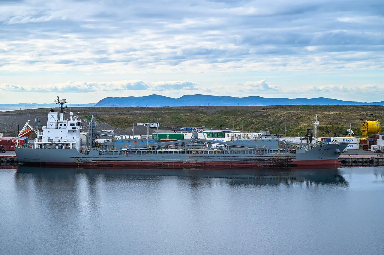
A cement carrier is a specialized type of bulk carrier engineered to transport fine, powdery materials—most commonly cement, but also fly ash, ground blast furnace slag, and limestone powder—without environmental contamination or cargo loss. Unlike standard bulk carriers that rely on shore-based cranes or grabs to discharge cargo, cement carriers are characterized by their ability to perform self-unloading.
For a broader context on different maritime vessel types, see our reports on Bulk Carriers and Container Ships.
The defining feature of these vessels is their enclosed material handling system. Because the cargo is extremely fine (often measured in microns), any exposure to the atmosphere during loading or unloading would result in massive dust clouds, posing severe health risks to crew and shore workers and causing significant environmental pollution. To mitigate this, cement carriers utilize highly sophisticated pneumatic and mechanical systems that operate within a closed-loop, often under vacuum, to ensure “dust-free” operations.
These vessels play a critical role in the global construction supply chain, acting as the primary link between cement production plants and regional distribution terminals, particularly in coastal regions of Asia, Europe, and North America.
2. Mission and Operations
The primary mission of a cement carrier is the reliable, weather-independent delivery of dry bulk cement to specialized terminals. Their operations are divided into several key phases:
Loading
Loading is typically a “closed” process. Shore-based pneumatic systems or specialized conveyors pump the cement into the ship’s holds. The ship’s dust collection system is active during this phase to maintain a slight negative pressure (vacuum) within the holds, ensuring that any displaced air is filtered through the ship’s dust collectors before being vented to the atmosphere.
Transit
During transit, the cargo must remain stable. While cement is generally considered a non-liquefying cargo under standard conditions, the design of the holds and the potential for moisture ingress must be strictly managed to prevent “caking” or unplanned fluidization which could lead to cargo shift.
Unloading (Self-Discharge)
This is the core competency of the vessel. Depending on the ship’s design, unloading is performed via one of two primary methods:
- Pneumatic Discharge: The most common method for smaller and medium-sized vessels. High-pressure air is used to “fluidize” the cargo, turning the powder into a pseudo-liquid state that can be pumped through blow-lines directly into shore silos.
- Mechanical Discharge: Often used in larger vessels or in combination with pneumatic systems. This involves internal screw conveyors (augers) that move the cargo from the hold to a central discharge point or a ship’s boom.
The ability to discharge without shore-side assistance allows these vessels to service remote or underdeveloped ports, providing immense logistical flexibility.
3. Hull, Size, and Design
Cement carriers are generally smaller and more specialized than the massive Capesize or Panamax bulk carriers used for iron ore or coal. Their design is dictated by the need for specialized cargo holds and efficient discharge machinery.
Typical Dimensions and Capacity
- Deadweight Tonnage (DWT): Most vessels fall within the 5,000 to 20,000 DWT range. Smaller coastal carriers may be as low as 2,000 DWT, while larger specialized carriers can reach up to 30,000 DWT or more.
- Length Overall (LOA): Typically ranges from 60 meters to 160 meters.
- Breadth (Beam): Generally between 10 and 26 meters.
Hold Design and Compartmentalization
The cargo holds of a cement carrier are significantly different from standard bulk holds:
- Enclosure: Holds are designed to be airtight or near-airtight to facilitate vacuum-based dust control.
- Fluidization Surface: The bottom of the holds is often equipped with aeration pads or porous membranes. These surfaces allow air to be injected into the cargo mass from beneath.
- Compartmentalization: Holds are often subdivided to manage cargo weight distribution and to allow for partial discharge if necessary.
Stability Considerations
The design must account for the unique behavior of fine powders. While cement does not “liquefy” in the same way as ores like nickel ore, the process of fluidization during discharge temporarily changes the cargo’s physical properties. Engineers must ensure that the ship’s center of gravity and the effective “angle of repose” are managed to prevent sudden cargo shifts that could jeopardize vessel stability.
4. Propulsion and Engines
Because cement carriers are often used for coastal or regional trades, their propulsion systems are optimized for reliability and fuel efficiency at moderate speeds rather than the massive power required by ocean-going tankers or large bulkers.
Typical Engine Configurations
- Main Engine: Most vessels are powered by medium-speed, single or twin-engine diesel setups. Common manufacturers include MAN Energy Solutions, Wärtsilä, Mitsubishi, and MaK.
- Power Output: Depending on the vessel’s size, engine power can range from a few hundred to several thousand kilowatts.
- Service Speed: Typically operates at economical speeds of 10 to 14 knots, though some high-speed coastal carriers may exceed this.
Auxiliary Systems
A significant portion of the vessel’s power is dedicated to the cargo handling machinery. Large-capacity air compressors and rotary lobe blowers are critical components. These systems require robust electrical power to maintain the high pressures and vacuum levels necessary for both the cargo discharge and the dust filtration systems.
5. Electrical System and Power
The electrical architecture of a cement carrier is uniquely burdened by the continuous demand of its cargo-handling subsystems.
High-Demand Subsystems
- Pneumatic Blowers: Large rotary lobe blowers require significant starting torque and sustained power to maintain the 450–950 CFM (Cubic Feet per Minute) required for discharge.
- Dust Collection Units: The heavy-duty motors used to drive the suction fans for the hold vacuum systems.
- Air Compressors: Providing the “service air” required for pneumatic valves and the reverse-jet cleaning of filter elements.
- Pneumatic Control Systems: A network of solenoid valves and actuators that manage the flow of air to aeration pads, blow-lines, and dust collectors.
Power Management
To prevent cargo discharge interruptions—which can lead to expensive “line plugs”—the electrical system must be highly redundant. Most modern vessels employ an automated power management system (PMS) to prioritize cargo-handling loads over non-essential services during discharge operations.
6. Equipment and How It Is Used
The heart of the cement carrier lies in its dual-mode unloading capability. The following table compares the two primary methods used in the industry.
Comparison of Unloading Systems
| Feature | Pneumatic Discharge | Mechanical Discharge |
|---|---|---|
| Primary Mechanism | Compressed air (Fluidization) | Screw conveyors / Augers |
| Cargo State | “Liquid-like” fluidized powder | Solid mass moved mechanically |
| Automation | High; easily controlled via pressure | Moderate; requires mechanical movement |
| Dust Control | Excellent; fully enclosed lines | Good; requires enclosed conveyors |
| Complexity | High (requires blowers & compressors) | Moderate (mechanical moving parts) |
| Typical Use Case | Small to Medium vessels; remote ports | Large vessels; high-volume terminals |
| Risk Factor | Line blockage/plugging | Mechanical wear/jamming |
Detailed Component Breakdown
1. Pneumatic Components
- Blow-Lines: Large-diameter pipes that carry the fluidized cement from the hold to the shore.
- Aeration Pads: Porous canvas or silicone pads located at the bottom of the holds. When air is pumped through them, they create a “fluidized bed,” reducing the cargo’s internal friction and allowing it to flow toward the discharge point.
- Rotary Lobe Blowers: The “heart” of the pneumatic system, providing the necessary air volume and pressure.
- Pinch Valves: Specialized valves used to control the flow of highly abrasive cement powder without clogging.
2. Mechanical Components
- Screw Conveyors (Augers): Often made of high-strength, wear-resistant steel, these move cement through enclosed tubes. They are essential for moving cargo from the hold floor to the discharge manifold.
- Bellows: Flexible joints in the conveyor system that accommodate vessel movement and vibration.
3. Dust Management Components
- Dust Collectors: Large units (often 3 to 4 per vessel) that maintain a vacuum in the holds and conveyors.
- Filter Elements: High-efficiency bags or cartridges that trap fine cement particles.
- Reverse Jet System: A system that periodically blasts compressed air in reverse through the filters to shake off collected dust, keeping the filters clean and efficient.
7. Navigation, Communications, and Safety
While cement carriers carry standard maritime navigation and communication equipment (Radar, ECDIS, AIS, GMDSS), they require specialized safety protocols related to their unique cargo and operational environment.
Specialized Safety Protocols
- Vacuum/Pressure Safety: Crew must be trained in managing the critical pressure ratios between the hold and the discharge lines. A sudden equalization of pressure can cause catastrophic line failure or “blow-outs.”
- Dust Explosion Prevention: Fine cement dust is potentially explosive when suspended in air in certain concentrations. All electrical equipment in cargo areas must be “Ex” (explosion-proof) rated, and grounding protocols must be strictly followed to prevent static discharge.
- Respiratory Protection: During maintenance or in the event of a system leak, specialized PPE (Personal Protective Equipment), including high-grade respirators, is mandatory.
Navigation Challenges
Because many cement carriers operate in coastal, tidal, or riverine environments (e.s., Southeast Asia or the Great Lakes), they are often equipped with enhanced maneuvering capabilities, such as bow thrusters or even azimuth propulsion, to assist in tight docking maneuvers at specialized cement terminals.
8. Crew and Organization
The crew of a cement carrier is typically smaller than that of a large tanker but requires a higher degree of technical specialization regarding cargo handling.
Key Roles
- Chief Officer: Heavily involved in the supervision of cargo operations, ensuring the stability of the vessel and the correct management of the aeration/unloading sequences.
- Engine Department: Responsible for the critical maintenance of the blowers, compressors, and the electrical systems that power the cargo machinery. A failure in the engine room can immediately halt cargo operations.
- Specialized Cargo Operators: On larger or highly automated vessels, dedicated personnel may be assigned specifically to manage the pneumatic control systems and dust collection monitoring.
Training Requirements
Crew members must undergo specialized training (often supplemented by manufacturer-specific instruction) regarding:
- Fluidization physics and aeration control.
- Dust-free operation and vacuum management.
- Emergency procedures for “line plugging” and pressure spikes.
- Handling of hazardous/fine powders and respiratory safety.
9. Certificates and Training Requirements
Operating a cement carrier involves compliance with both general maritime regulations and specific cargo-handling standards.
Mandatory Maritime Certifications
- STCW Compliance: All crew must hold standard International Convention on Standards of Training, Certification, and Watchkeeping for Seafarers certifications.
- SOLAS/MARPOL: Compliance with Safety of Life at Sea and Marine Pollution regulations is fundamental.
Specialized Certifications
- Cargo Handling Endorsements: Crew may require specific endorsements for handling “Fine Bulk” or “Pneumatic Cargoes.”
- Manufacturer Training: Due to the complexity of systems like MacGregor’s handling arrangements, crew often receive direct training from the equipment manufacturers to operate the automation and maintenance protocols correctly.
- Dust Safety Training: Specific training on the hazards of combustible dust and the operation of dust-suppression/filtration systems.
10. Regulations, Class, and Inspections
Cement carriers are subject to rigorous inspection regimes to ensure the integrity of their enclosed systems and the safety of their specialized machinery.
Classification Societies
Vessels are typically classed by major societies such as DNV (Det Norske Veritas), Lloyd’s Register (LR), ABS (American Bureau of Shipping), or Bureau Veritas (BV). These societies establish the rules for:
- Structural Integrity: Ensuring the hull can withstand the unique stresses of pneumatic discharge and localized weight shifts.
- Machinery Standards: Validating the reliability of blowers and compressors.
- Environmental Compliance: Verifying that dust collection systems meet international standards for preventing air pollution.
Key Inspection Areas
- Vacuum Integrity Tests: Periodic testing of the holds and conveyor systems to ensure no air ingress occurs, which would compromise dust control.
- Aeration System Inspection: Checking for wear in the porous pads or canvas to prevent “hot spots” or uneven fluidization.
- Filter Integrity: Regular inspection of the dust collector filter elements and the “Reverse Jet” cleaning mechanism.
- Pressure Relief Systems: Ensuring that safety valves on the pneumatic lines and holds are fully operational to prevent over-pressurization.
11. Notable Shipyards, Operators, and Example Vessels
The cement carrier market is dominated by specialized operators in Asia and Europe, with shipyards in Japan and South Korea being leading builders.
Major Operators
- KGJ Cement (Kristian Gerhard Jebsen Group): One of the world’s largest independent operators, with a significant fleet of specialized cement carriers.
- CSL Group: A major player in the global bulk and specialized cargo market.
Notable Shipyards
- Sasebo Heavy Industries (Japan)
- Kanda Kawajiri (Japan)
- Shanhaiguan Shipbuilding (China)
- Shin Kurushima Shipyard (Japan)
Example Vessels
The following is a selection of representative cement carriers:
| Vessel Name | Operator/Type | Flag | DWT (Approx) |
|---|---|---|---|
| ADVAITA | Cement Carrier | Singapore | 22,700 |
| NACC PROVIDENCE | Cement Carrier | Panama | 20,200 |
| TAKAOKI MARU | Cement Carrier | Japan | 18,500 |
| GLORY ATLANTIC | KGJ Cement | Singapore | ~10,000 |
| WINTERSET | Cement Carrier | Marshall Is. | 23,570 |
| CEMCOASTER | Cement Carrier | - | 4,916 |
12. Environment and Future Outlook
The cement carrier industry is evolving toward higher levels of automation and stricter environmental compliance.
Environmental Impact and Mitigation
The primary environmental concern is dust emission. As global regulations on air quality (such as IMO’s MARPOL Annex VI and various national standards) become more stringent, the industry is moving toward:
- Ultra-High Efficiency Filtration: The adoption of advanced ceramic or nano-fiber filters in dust collectors.
- Zero-Leakage Systems: Moving toward fully integrated, “closed-loop” systems where every transfer point is hermetically sealed.
Future Trends
- Increased Automation: The move toward “unmanned” or “remote-monitored” cargo operations, where the entire unloading sequence is controlled by AI-driven software that optimizes air pressure and flow rates in real-time.
- Hybrid Propulsion: As coastal vessels face stricter emission zones, the integration of hybrid-electric propulsion systems to power heavy-duty blowers and compressors more efficiently is becoming a key area of research.
- Digital Twins: Using sensor data from aeration pads and blow-lines to create “digital twins” of the cargo hold, allowing operators to predict “plugs” before they occur.
13. Facts, Records, and Common Misconceptions
Facts
- The Vacuum Principle: Most modern dust-free operations are achieved not by “blowing air out,” but by keeping the entire system under a slight vacuum, which pulls dust into the filters rather than letting it escape.
- The Ratio Rule: A critical operational fact is that the tank (hold) pressure must always be 2 to 4 PSI higher than the line pressure to maintain velocity and prevent blockages.
Common Misconceptions
- “Cement is just like sand”: Many assume cement behaves like other dry bulks. However, the fine particle size means it can “clog” or “plug” lines instantly if the pressure ratio is incorrect, a risk not present with sand or grain.
- “Pneumatic is always better”: While pneumatic is more automated, mechanical systems (screw conveyors) are often more robust for much larger vessels where the energy required to fluidize a massive hold is prohibitively high.
14. Glossary
- Aeration: The process of injecting air into a cargo mass to reduce its density and friction.
- Blow-line: The specialized piping used to transport fluidized cargo from the ship to the shore.
- DWT (Deadweight Tonnage): The total weight a ship can safely carry, including cargo, fuel, and water.
- Fluidization: A state where a granular material (like cement) behaves like a liquid due to upward air flow.
- Mechanical Unloading: The use of physical moving parts (like augers) to transport cargo.
- Pneumatic Unloading: The use of air pressure and suction to move cargo.
- Pinch Valve: A valve that uses a flexible sleeve to stop flow, ideal for abrasive powders.
- Reverse Jet Cleaning: A method of cleaning dust filters by blasting air in the opposite direction of the flow.
- Screw Conveyor: A device used to move bulk materials using a rotating helical screw within a tube.
- Vacuum System: A system designed to maintain negative pressure within a space to prevent air/dust escape.
15. Sources
- MacGregor: Self-unloading systems
- Dry Cargo Magazine: Self-unloading vessels offering flexibility and autonomy
- MarineLink: KGJ Cement Fleet Management
- Scribd: Cement Carrier Technical Documentation
- VesselFinder: Cement Carrier Specifications and Vessel Lists