1. What Is This Ship?
The electric hydrofoil passenger vessel represents a transformative convergence of two high-impact maritime technologies: high-efficiency hydrofoil lift and high-energy-density electric propulsion. For decades, maritime transport has been dominated by two paradigms: displacement hulls, which are efficient at low speeds but face massive resistance as they accelerate, and planing hulls, which can achieve high speeds but do so with a massive penalty in energy consumption and wake production.
Hydrofoil technology introduces a third paradigm: “flight” above the water. By utilizing underwater wings—foils—to generate lift, these vessels can raise their entire hull out of the water, effectively bypassing the majority of hydrodynamic drag. When this efficiency is paired with the rapid decarbonization of the maritime sector via electric propulsion, a new class of vessel emerges. These are not merely “boats with foils”; they are highly sophisticated, computer-controlled maritime aircraft that operate in a fluid medium.
This technology is particularly relevant when compared to traditional High-Speed Passenger Ferries, which often rely on heavy diesel engines and high-drag hull forms. As cities and nations push toward net-zero targets, the electric hydrofoil offers a path to high-speed connectivity that is both ecologically responsible and economically viable.
2. Mission and Operations
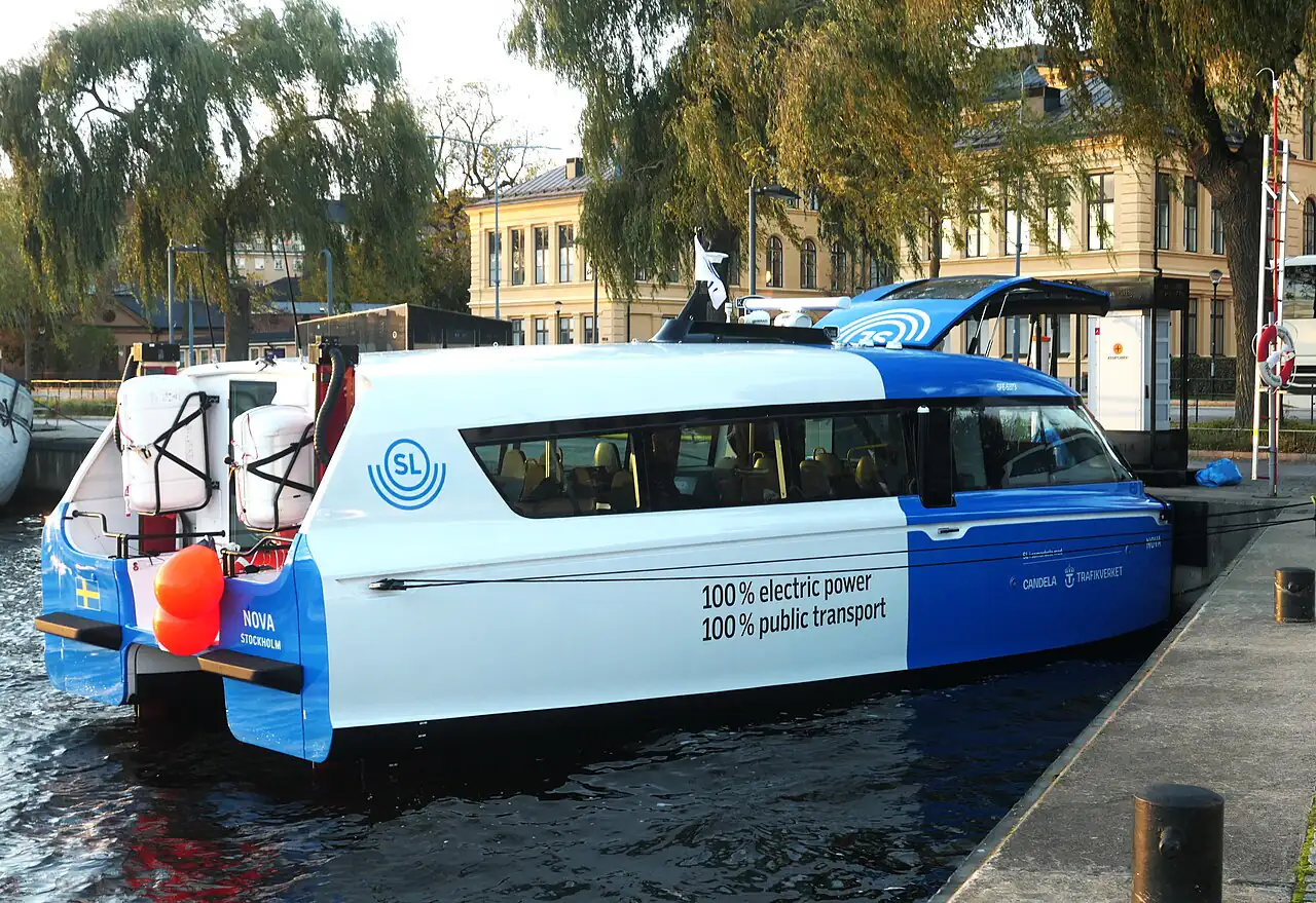
The mission of electric hydrofoil passenger vessels is to provide rapid, reliable, and zero-emission transit for passengers in environments where traditional high-speed vessels are either too loud, too disruptive, or too polluting.
Key Operational Profiles
- Urban Micro-Mobility: In densely populated coastal cities, these vessels act as high-speed water taxis. Their ability to operate with minimal wake makes them ideal for navigating through busy harbors, near historic piers, and along urban waterfronts without causing structural damage from wave action.
- Inter-Island Logistics: In archipelago nations, they serve as vital links for both tourism and local commerce. The ability to maintain high speeds even in moderate sea states—thanks to active foil control—makes them more reliable than small traditional boats.
- Premium Tourism: The “flight” sensation provides a unique passenger experience. The reduction in vibration and engine noise creates a luxury environment, making them highly attractive for high-end sightseeing and excursions.
- Eco-Sensitive Transit: In protected marine sanctuaries, these vessels can operate where diesel-powered craft are restricted or banned due to their acoustic signature and chemical emissions.
Unlike a massive Cruise Ship that is designed for long-duration stability and immense capacity, the electric hydrofoil is optimized for “burst” transit—getting passengers from point A to point B as quickly and cleanly as possible.
3. Hull, Size, and Design
The design of an electric hydrofoil vessel is an exercise in balancing conflicting hydrodynamic requirements. The goal is to design a hull that is stable during low-speed maneuvering (displacement mode) but becomes an efficient “wing” at cruising speeds (foiling mode).
Comparison of Maritime Hull Paradigms
| Feature | Displacement Hull | Planing Hull | Hydrofoil (Full-Foiling) |
|---|---|---|---|
| Primary Lift | Buoyancy (Archimedes) | Hydrodynamic Pressure | Hydrofoil Lift (Bernoulli) |
| Drag Profile | High (Wave-making) | Moderate (Skin/Pressure) | Low (Minimal Wetted Area) |
| Speed Range | Low | Moderate to High | High |
| Wake Impact | High | Very High | Very Low |
| Energy Efficiency | High (at low speed) | Low (at high speed) | Very High (at high speed) |
Design Nuances
- Foil Geometry & Aspect Ratio: A high aspect ratio (long, slender foils) is preferred for minimizing induced drag, similar to the wings of a glider. However, these foils are more prone to cavitation and are more sensitive to changes in the angle of attack.
- The Strut-Hull Interface: The connection between the foils and the hull (the struts) is a critical design point. These must be strong enough to handle the intense bending moments during “flight” but streamlined enough to minimize drag when the vessel is in displacement mode.
- Stability and Pitch Control: Because the center of lift and the center of buoyancy rarely coincide perfectly, hydrofoil vessels are inherently prone to pitching. This necessitates complex, high-frequency control surfaces (flaps) on the foils.
4. Propulsion and Engines
The propulsion of an electric hydrofoil is a holistic system that includes the energy source, the motor, and the hydrodynamic interface.
Hydrofoil Lift Physics
The “magic” of the hydrofoil lies in the manipulation of fluid pressure. According to Bernoulli’s Principle, as the velocity of a fluid increases, its pressure decreases. A foil is shaped such that the water traveling over the top surface must move faster than the water underneath, creating a low-pressure zone on top and a high-pressure zone below. This pressure differential generates the upward lift.
The efficiency of this process is captured by the Lift-to-Drag (L/D) Ratio. For a well-designed marine foil, this ratio can be significantly higher than that of a hull.
| Angle of Attack (AoA) | Lift Force | Drag Force | Efficiency Note |
|---|---|---|---|
| 0° | Minimal | Very Low | Baseline |
| 3° – 4° | High | Low | Optimal L/D Ratio |
| 10° | Extremely High | High | High lift, but high drag penalty |
| >15° | Stall | Extremely High | Sudden loss of lift; dangerous |
Electric Motor Technology
Traditional marine engines use complex gearboxes and heavy fuel systems. Electric hydrofoils leverage:
- Permanent Magnet Synchronous Motors (PMSM): These offer extremely high power density and efficiency (often >95%).
- Electric Pods (e.g., Candela C-Pod): By placing the motor and propeller in a steerable pod underwater, designers can achieve precise thrust vectoring, which assists the flight control system in maintaining stability.
- Direct Drive vs. Geared: Many electric systems move toward direct-drive configurations to reduce mechanical complexity and friction losses.
5. Electrical System and Power
The transition from diesel to electric is essentially a transition from “energy density in fuel” to “energy density in batteries.”
Battery Architecture
For a high-speed vessel, the battery system must not only store energy but also deliver massive amounts of power on demand (high C-rate).
- Energy Density Challenges: Current Li-ion technology provides roughly 250–300 Wh/kg. While this is much lower than diesel, the hydrofoil’s reduced drag means the vessel requires far less energy per mile than a displacement vessel.
- Cell Chemistry: Nickel Manganese Cobalt (NMC) or Lithium Iron Phosphate (LFP) are common choices. NMC offers higher density for speed, while LFP offers better cycle life and safety.
- Thermal Management: High-power discharge generates significant heat. Integrated liquid cooling systems are required to maintain battery temperature and prevent thermal runaway.
DC Power Distribution
Most modern electric vessels utilize a High-Voltage DC (HVDC) Grid.
- Efficiency: DC distribution avoids the losses associated with multiple AC/DC conversions.
- Integration: It allows for a more direct connection between the battery, the motor controllers (inverters), and the charging station.
- Charging: Ultra-fast DC charging (up to 300kW or more) is critical to minimize “turnaround time” in commercial ferry operations.
6. Equipment and How It Is Used
The hardware of a hydrofoil vessel is a mix of heavy structural elements and precision electronic instruments.
Primary Hardware
- Hydrofoils: The primary lifting surfaces, typically constructed from high-strength aluminum, stainless steel, or advanced carbon fiber composites.
- Flight Control Actuators: High-speed, high-torque electric actuators that move the foil flaps to maintain pitch and roll stability.
- Electric Propulsion Units: The motors and propellers that drive the vessel forward.
- Battery Energy Storage System (BESS): The modular battery banks that provide the vessel’s power.
Sensor Suite (The “Eyes” of the Vessel)
To maintain stable flight, the vessel’s computer requires a constant stream of high-fidelity data:
- Inertial Measurement Units (IMUs): High-frequency sensors that detect pitch, roll, and heave.
- Depth/Altitude Sensors: Ultrasonic or pressure-based sensors that measure the distance from the foil to the seabed.
- Speed Sensors: Pitot tubes or Doppler velocity logs (DVL) to measure speed through the water.
- Environmental Sensors: Wind and wave sensors to anticipate disturbances.
7. Navigation, Communications, and Safety
Navigation in a foiling vessel is a hybrid of traditional maritime practice and advanced digital flight management.
Active Flight Control Systems
The most critical safety component is the Flight Control Computer (FCC). This system must manage the vessel’s stability in real-time.
| Algorithm Type | Mechanism | Best Use Case |
|---|---|---|
| PID Control | Reacts to the difference between current and desired state. | Standard stability and altitude hold. |
| Sliding Mode (SMC) | Uses nonlinear control to “force” the system onto a stable surface. | Handling sudden wave impacts or gusts. |
| Model Predictive (MPC) | Predicts future states based on a mathematical model. | Optimization of flight paths and energy use. |
Safety Systems
- Failsafe Transition: In the event of a computer or sensor failure, the vessel must be designed to automatically transition to a safe “displacement mode” where it can be steered manually.
- Redundancy: Critical flight and propulsion systems must have “dual-channel” or “triple-modular” redundancy.
- Communication: Integration with AIS and satellite-based navigation is mandatory for commercial operation.
8. Crew and Organization
The high degree of automation in electric hydrofoils is redefining maritime labor.
Crewing Models
- Autonomous/Semi-Autonomous: For smaller shuttles, the vessel may be operated by a single captain with significant computer assistance, or even remotely monitored from a shore-based operations center.
- Traditional Commercial Crew: For larger passenger ferries, a standard crew (Captain, First Mate, Engineer) is still used, but their roles shift from manual mechanical management to digital system monitoring and passenger safety.
Training
Crew training for foiling vessels is specialized. It focuses on:
- Flight Envelope Awareness: Understanding the limits of the foil’s lift and the dangers of “stalling.”
- Electrical Safety: Handling high-voltage systems and emergency battery procedures.
- Software Proficiency: Operating the advanced interfaces used to manage flight and propulsion.
9. Certificates and Training Requirements
Compliance with international and national standards is a prerequisite for commercial operation.
Key Certifications
- IMO High Speed Craft (HSC) Code: Provides the international standard for the construction and operation of high-speed vessels.
- Classification Society Notations: Companies like DNV provide specific “notations” (e.g., Electric Propulsion, Hydrofoil, Battery) that certify the vessel meets rigorous technical standards for those specific technologies.
Training Requirements
- Type-Specific Training: Operators must undergo training specific to the vessel’s flight control system and battery management architecture.
- Safety Management Systems (SMS): Operators must implement SMS that accounts for the unique risks of high-speed foiling and high-voltage electricity.
10. Regulations, Class, and Inspections
The regulatory landscape for electric hydrofoils is rapidly maturing.
- Class Societies (DNV, LR, ABS): These organizations act as the primary technical auditors. They set the rules for hull integrity, foil fatigue, and electrical safety.
- Environmental Regulations: As IMO regulations on decarbonization tighten, hydrofoils are being positioned as the “gold standard” for compliant high-speed transit.
- Inspection Protocols:
- Foil Inspection: Regular ultrasonic or visual inspections to check for fatigue cracks or cavitation damage.
- Battery Health Monitoring: Continuous monitoring of cell voltage, resistance, and temperature to ensure the BESS is safe and efficient.
- Control System Audits: Verifying the integrity of the flight control software and sensor calibration.
11. Notable Shipyards, Operators, and Example Vessels
The industry is currently led by a few highly specialized innovators.
Leading Examples
| Vessel Name | Manufacturer | Capacity | Performance Note |
|---|---|---|---|
| Candela P-12 Shuttle | Candela | 30 PAX | High efficiency for urban transit. |
| Artemis EF-24 Passenger | Artemis Technologies | 150 PAX | High-speed, large-capacity foiling. |
| Artemis EF-12 Escape | Artemis Technologies | 50 PAX | Mid-range versatile foiling. |
Key Industry Players
- Candela (Sweden): Focused on the “electric shuttle” market, prioritizing ease of integration into existing ferry infrastructure.
- Artemis Technologies (UK): Focused on large-scale, high-speed foiling technology for the global ferry and luxury markets.
12. Environment and Future Outlook
The environmental impact of electric hydrofoil vessels extends beyond just “zero emissions.”
Ecological Benefits
- Wake Reduction: By lifting the hull, these vessels drastically reduce the energy transferred to the water surface. This preserves shorelines from erosion and minimizes the disruption of aquatic habitats.
- Acoustic Footprint: Electric motors are significantly quieter than diesel engines, reducing underwater noise pollution—a major concern for marine mammals.
The Future of Maritime Transport
As we look toward 2050, the “electric hydrofoil” is likely to become a standard for all short-to-medium range high-speed transit. Key drivers will include:
- Solid-State Batteries: Offering even higher energy densities and improved safety.
- Autonomous Operations: Allowing for more efficient, scheduled, and cost-effective transit.
- Global Decarbonization: The inevitable shift away from fossil fuels in the maritime sector.
13. Facts, Records, and Common Misconceptions
Common Misconceptions
- “High speed means high energy use”: For a displacement vessel, this is true. For a hydrofoil, the drag-reduction benefits often mean that increasing speed from 15 to 25 knots results in a much smaller energy penalty than it would for a traditional boat.
- “They are too fragile for the ocean”: Modern foils are engineered to handle significant sea states, with many designed to operate in waves up to 2.5–4 meters.
Key Performance Fact
The transition from diesel to electric hydrofoils can lead to an operational cost reduction of 24% to 36%, primarily due to the elimination of fuel costs and the reduction in mechanical maintenance.
14. Glossary
- Angle of Attack (AoA): The angle between the chord line of a foil and the incoming flow.
- C-Pod: A specialized electric propulsion pod developed by Candela.
- Displacement Mode: The state where the hull is supported by buoyancy.
- eFoiler®: Proprietary hydrofoil technology by Artemis Technologies.
- L/D Ratio: The lift-to-drag ratio, a measure of aerodynamic/hydrodynamic efficiency.
- PMSM: Permanent Magnet Synchronous Motor.
- Sliding Mode Control (SMC): A robust nonlinear control strategy for stability.
- Stall: The loss of lift due to an excessive angle of attack.
- Strut: The vertical structural member connecting the foil to the hull.
- Wake: The disturbance in water left behind by a moving vessel.